How to Measure Ground Resistance with a Multimeter
Experiments were conducted using a multimeter to measure ground resistance in different soil types, and the data obtained from the multimeter was compared with that from a specialized ground resistance tester, showing very close results. The specific measurement method is as follows:
Find two pieces of 8mm, 1m long round steel, sharpen one end to use as auxiliary test rods, and insert them underground 5m away from both sides of the grounding body A, with a depth of at least 0.6m, ensuring that all three points are in a straight line.
Here, A is the grounding body to be tested, and B and C are the auxiliary test rods.
Then use the multimeter (on the R*1 setting) to measure the resistance values between A and B; and A and C, denoting them as RAB, RAC, and RBC respectively. By calculating these, you can determine the ground resistance of body A.
The ground resistance refers to the contact resistance between the grounding body and the soil. Let the ground resistances of A, B, and C be RA, RB, and RC respectively. Let the resistance of the soil between A and B be RX. Because the distances AC and AB are equal, the soil resistance between A and C is also RX; and since BC = 2AB, the soil resistance between B and C is approximately 2RX, thus:
RAB = RA + RB + RX…
①RAC = RA + RC + RX…
②RBC = RB + RC + 2RX…
③By combining equations ① + ② – ③, we get: RA = (RAB + RAC – RBC) / 2…
④This equation is the calculation formula for ground resistance.
Measured example: The data obtained for a certain grounding body is as follows: RAB = 8.4Ω, RAC = 9.3Ω, RBC = 10.5Ω. Thus:
RA = (8.4 + 9.3 – 10.5) / 2 = 3.6 (Ω)
Therefore, the ground resistance value of the tested grounding body A is 3.6Ω.
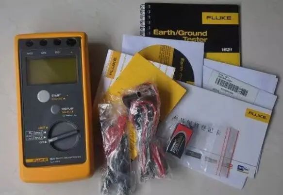
Why is a smaller ground resistance better?
The smaller the resistance, the less resistance there is to the current flow. Therefore, in the case of leakage, the current will fully transfer from the grounding line to the ground.
There are many types of grounding, such as lightning protection grounding (commonly known as lightning rods): a smaller ground resistance means that when struck by lightning, the discharge through the grounding wire to the ground occurs faster, thus being safer; for electrical equipment grounding (like the casing of a washing machine): a smaller ground resistance ensures that in case of leakage, the leakage current will flow into the ground through the grounding wire. If the ground resistance is too high (for example, greater than the resistance of the human body), when a person touches the casing, the body becomes the grounding wire, and the current flows from the body into the ground, leading to electric shock; and there are also working grounds inside electronic devices, etc., where smaller is better.


To help everyone learn better, Changxue Electronics has specially added a public account focused on microcontrollers and EDA, pushing relevant knowledge daily, hoping to assist your learning!