
Click the blue text
Follow us
1. Introduction to SPI
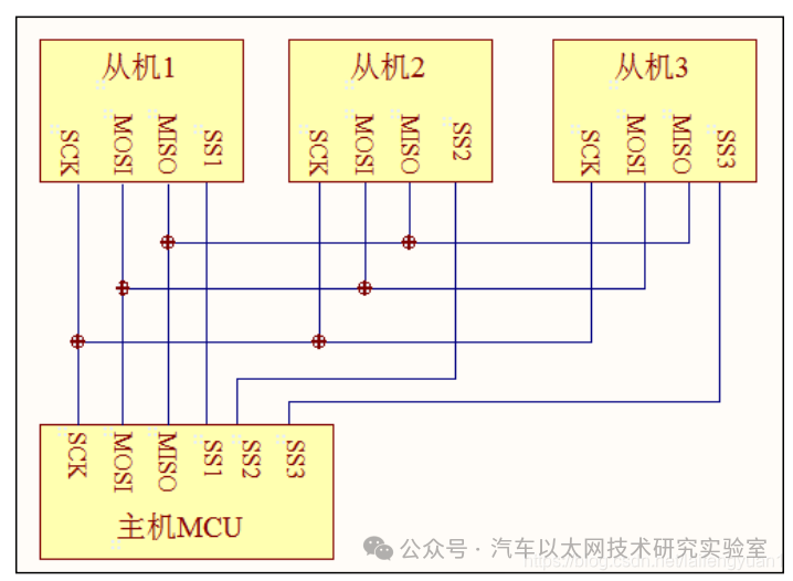
1. SPI Physical Layer
SPI generally uses 4 lines for communication:
-
NSS: Chip select line
-
MOSI: Master data output, slave data input
-
MISO: Master data input, slave data output
-
SCK: Clock line, provided by the master
2. Protocol Layer
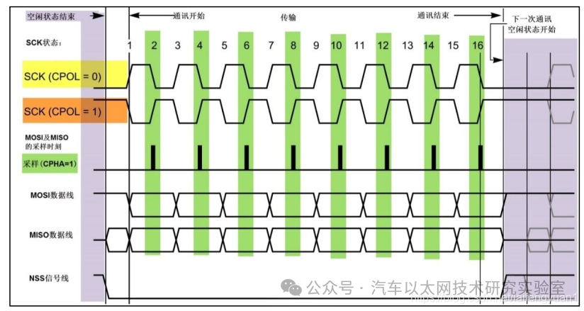
(1) Basic SPI Communication Timing
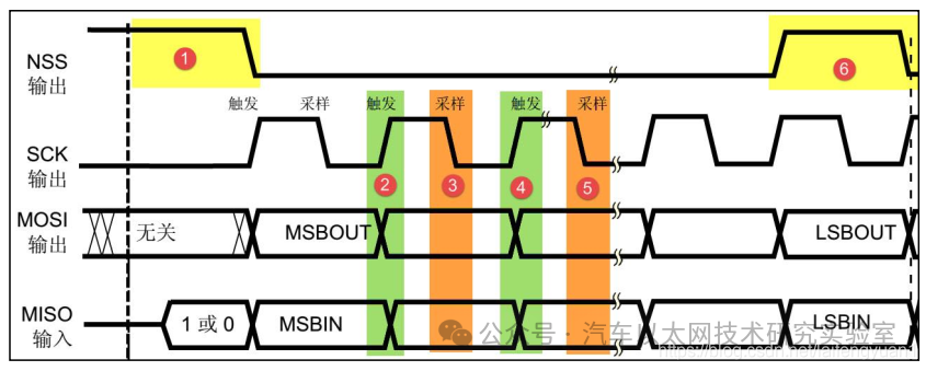
(2) Start and Stop Signals
-
Start signal: NSS goes from high to low
-
Stop signal: NSS goes from low to high
(3) Data Validity
-
SPI uses the SCK line for data synchronization, with MOSI and MISO transmitting one bit of data during each clock cycle of SCK, and the input and output of data occurring synchronously
-
During data transmission, it is generally adopted that the MSB is sent first (high byte first, then low byte)
-
Each data transmission in SPI can be in units of 8 bits or 16 bits, with no limit on the number of units transmitted each time
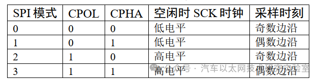
(4) Four Communication Modes of SPI (CPOL – Clock Polarity and CPHA – Clock Phase)
-
Clock Polarity CPOL: Indicates the level of SCK when idle. (e.g., CPOL = 0 —- SCK idle state is low; CPOL = 1 —- SCK idle state is high)
-
Clock Phase CPHA: Indicates when data is sampled. (e.g., CPHA = 0 —- data is sampled on the odd edge of SCK; CPHA = 1 —- data is sampled on the even edge of SCK)
Four modes of SPI:
When CPHA = 0 (SPI timing diagram with sampling edge on odd edge)
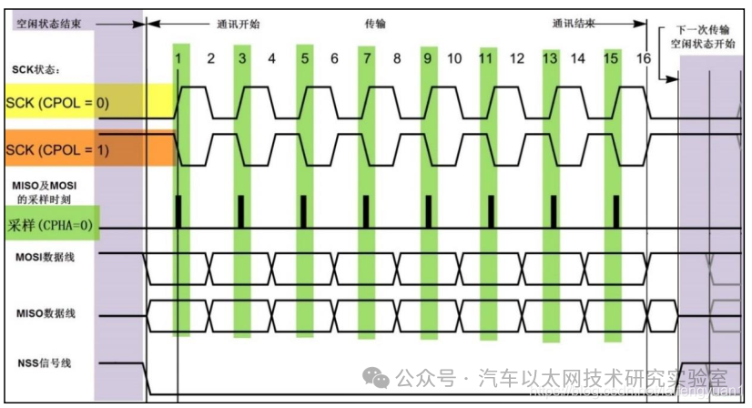
When CPHA = 1 (SPI timing diagram with sampling edge on even edge)
2. Software SPI Example
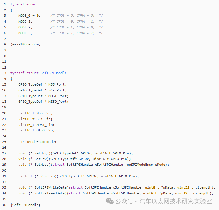
1. Software SPI Structure and SPI Mode Enumeration
2. SPI Initialization Function
-
void vSoftSPIInit(exSPIModeEnum eMode)
-
{
-
GPIO_InitTypeDef GPIO_InitStruct = {0};
-
/* Pin initialization */
-
SOFT_SPI_CLK_ENABLE();
-
/**SPI1 GPIO Configuration
-
PB14 ——> SPI1_NSS
-
PB3 ——> SPI1_SCK
-
PB4 ——> SPI1_MISO
-
PB5 ——> SPI1_MOSI
-
*/
-
GPIO_InitStruct.Pin = SOFT_SPI_NSS_PIN;
-
GPIO_InitStruct.Mode = GPIO_MODE_OUTPUT_PP;
-
GPIO_InitStruct.Pull = GPIO_NOPULL;
-
GPIO_InitStruct.Speed = GPIO_SPEED_FREQ_VERY_HIGH;
-
HAL_GPIO_Init(SOFT_SPI_NSS_PORT, &GPIO_InitStruct);
-
GPIO_InitStruct.Pin = SOFT_SPI_SCK_PIN;
-
HAL_GPIO_Init(SOFT_SPI_SCK_PORT, &GPIO_InitStruct);
-
GPIO_InitStruct.Pin = SOFT_SPI_MOSI_PIN;
-
HAL_GPIO_Init(SOFT_SPI_MOSI_PORT, &GPIO_InitStruct);
-
GPIO_InitStruct.Pin = SOFT_SPI_MISO_PIN;
-
GPIO_InitStruct.Mode = GPIO_MODE_INPUT;
-
HAL_GPIO_Init(SOFT_SPI_MISO_PORT, &GPIO_InitStruct);
-
/* Initialize Soft SPI handle */
-
ex_SoftSPIHandle.NSS_Port = ex_SoftSPIHandle.SCK_Port = ex_SoftSPIHandle.MISO_Port = ex_SoftSPIHandle.MOSI_Port = GPIOB;
-
ex_SoftSPIHandle.NSS_Pin = SOFT_SPI_NSS_PIN;
-
ex_SoftSPIHandle.SCK_Pin = SOFT_SPI_SCK_PIN;
-
ex_SoftSPIHandle.MOSI_Pin = SOFT_SPI_MOSI_PIN;
-
ex_SoftSPIHandle.MISO_Pin = SOFT_SPI_MISO_PIN;
-
/* Register Soft SPI functions */
-
ex_SoftSPIHandle.SetHigh = vSetHigh;
-
ex_SoftSPIHandle.SetLow = vSetLow;
-
ex_SoftSPIHandle.SetMode = vSetMode;
-
ex_SoftSPIHandle.ReadPin = HAL_GPIO_ReadPin;
-
ex_SoftSPIHandle.SoftSPIWriteData = vSoftSPIWriteData;
-
ex_SoftSPIHandle.SoftSPIReadData = vSoftSPIReadData;
-
/* Set corresponding SPI mode */
-
ex_SoftSPIHandle.mode = eMode;
-
if(eMode & MODE_0)
-
{
-
/* CPOL = 0 ; CPHA = 0 */
-
/* SPI default mode 0 is idle */
-
SOFT_SPI_NSS_High();
-
SOFT_SPI_SCK_Low();
-
}
-
else if(eMode & MODE_1)
-
{
-
/* CPOL = 0 ; CPHA = 1 */
-
/* SPI default mode 1 is idle */
-
SOFT_SPI_NSS_High();
-
SOFT_SPI_SCK_Low();
-
}
-
else if(eMode & MODE_2)
-
{
-
/* CPOL = 1 ; CPHA = 0 */
-
/* SPI default mode 2 is idle */
-
SOFT_SPI_NSS_High();
-
SOFT_SPI_SCK_High();
-
}
-
else
-
{
-
/* CPOL = 1 ; CPHA = 1 */
-
/* SPI default mode 3 is idle */
-
SOFT_SPI_NSS_High();
-
SOFT_SPI_SCK_High();
-
}
-
}
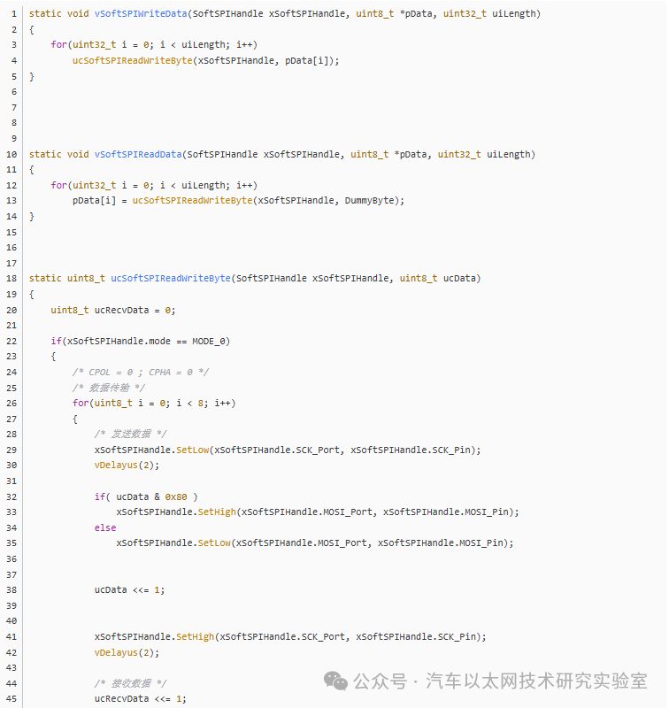
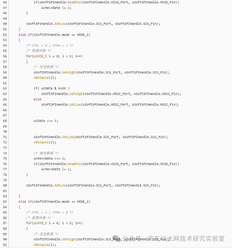
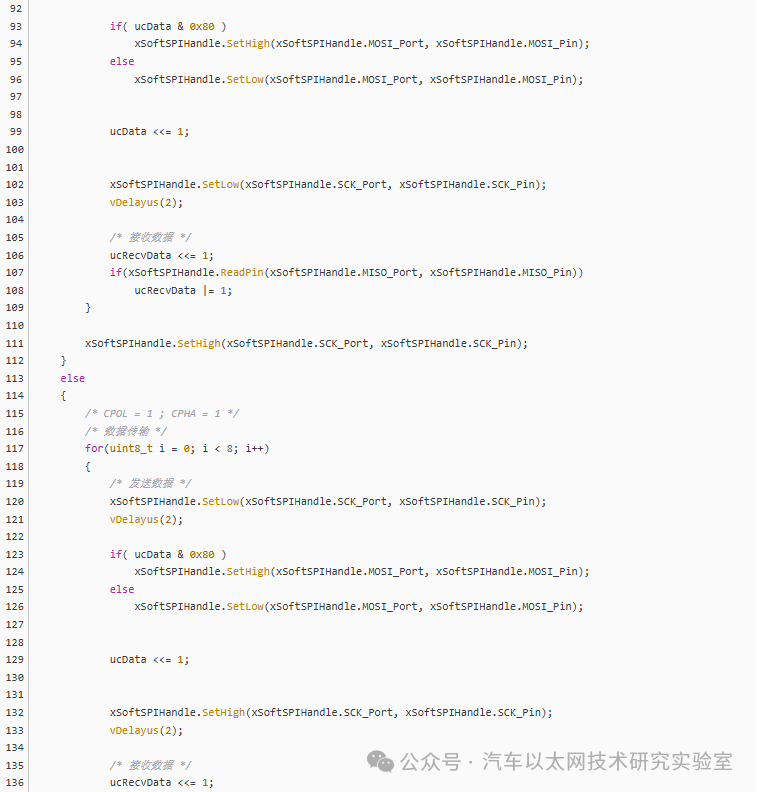
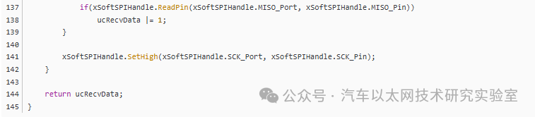
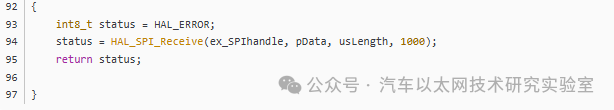
3. SPI Read/Write Functions
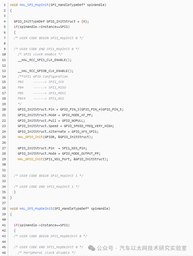
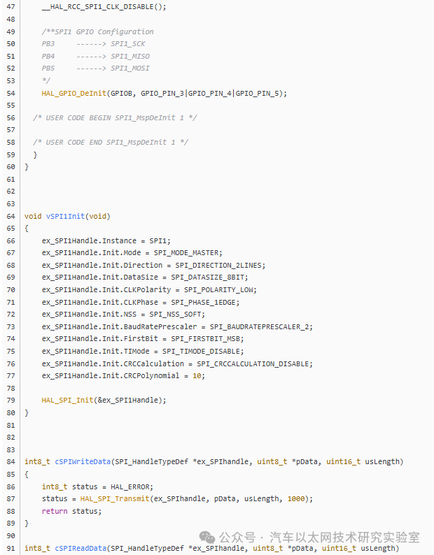
3. STM32-SPI Peripheral Usage Example (HAL Library)


*Disclaimer: This article is original or forwarded by the author. If it inadvertently infringes on someone’s intellectual property, please inform us for deletion.The above images and text are sourced from the internet. If there is any infringement, please contact us in a timely manner, and we will delete it within 24 hours.The content of the article represents the author’s personal views, and the Automotive Ethernet Technology Research Laboratory reprints it only to convey a different perspective, which does not represent the Automotive Ethernet Technology Research Laboratory’s endorsement or support of this view. If there are any objections, please feel free to contact the Automotive Ethernet Technology Research Laboratory.
Original link:
https://blog.csdn.net/laifengyuan1/article/details/110823739