Follow the blue text and reply with “entry materials” to get a tutorial from beginner to advanced on microcontrollers
Development boards will guide you in your journey
Written by | Wu Ji (WeChat: 2777492857)
The full text is about3518 words, reading will take about 15 minutes
Recall those long nights debugging when faced with a bizarre, illogical program bug that leaves you puzzled. Besides using a multimeter, oscilloscope, or emulator, who is the most frequently called “savior”?
Chances are, you would blurt out:Serial port! UART!
That’s right, the one that only requires three wires (TX, RX, GND, and sometimes even fewer) to print printf information on the PC terminal software and receive debugging commands. It is like the “universal solution” in the embedded world, simple, reliable, and ubiquitous.
However, the question arises: the communication interfaces commonly used in microcontrollers are not limited to UART!SPI and I2C are also capable of connecting sensors, memory, and expansion chips, often with higher speed and efficiency.
So why, in this specific scenario of debugging, are they rarely used, almost being overshadowed by UART? Is it because they are too “high-end” to engage in such “dirty work”? Or is there another reason?
Today, we will delve into why UART can firmly hold the “center stage” in embedded debugging, while SPI and I2C remain as “bystanders”.
1. UART: Simple and Direct, Striking at the Core
To understand why UART is so favored, we must look at its several “killer features” tailored for debugging.
1.Hardware Connection: Shockingly Simple
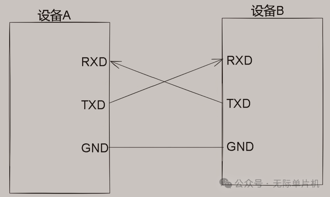
○Minimum Mode: Only one TX wire (from the microcontroller to the PC) and one GND wire can achieve the most basic printing debug information function. This is a boon for systems with tight pin resources.
○Standard Mode: Adding one RX wire (from the PC to the microcontroller) enables bidirectional communication, such as sending debugging commands to control program behavior. This can be done with 2-3 wires in total.
○Point-to-Point: UART is typically a point-to-point connection (one transmitter corresponds to one receiver), with a clear structure that minimizes bus conflicts. During debugging, you only need to focus on the “two-person world” between the microcontroller and your debugging host (usually a PC).
2.The Protocol Itself: Almost “Zero” Overhead
○Asynchronous Communication: UART is asynchronous, meaning it does not require an additional clock line to synchronize data. Both parties only need to agree on parameters such as baud rate, data bits, stop bits, and parity bits to “shout across the void”. This saves wires and simplifies timing matching issues.
○Bytes Reign Supreme: UART’s data transmission is based on bytes, making it very suitable for transmitting text information. The most commonly used function during debugging is printf, which outputs a stream of characters (byte stream). UART supports this natively.
○Software Implementation: Lightweight Player
▪Sending: On many microcontrollers, after configuring UART, sending a byte may only require writing to a data register, and the hardware will automatically handle the packaging and sending of start bits, data bits, and stop bits. Implementing a putc function is extremely simple, and printf relies on it seamlessly.
▪Receiving (optional during debugging): Receiving is slightly more complex, usually handled by interrupts, but it is relatively fixed and patterned. For many debugging scenarios that only print logs, you may not even need to care about receiving.
3.Seamless Integration with PC: This is the Game Changer!
○USB to Serial Modules: These are simply essential tools for embedded engineers. Ranging from a few dollars to several tens of dollars, one end connects to the microcontroller’s UART pins, and the other end connects to the PC’s USB port, instantly establishing a physical connection. The drivers are mature and plug-and-play.
○Standard COM Port: PC operating systems natively support COM ports (although physical COM ports are fewer, USB to serial will virtualize a COM port).
○The Universal Terminal Software: PuTTY, Tera Term, SecureCRT, XShell, sscom… countless free or paid terminal software can easily open COM ports, display the debugging information sent from the microcontroller in real-time, and send commands to the microcontroller. What you see is what you get, without the need to write any specialized host programs.
This combination of “low cost, low complexity, high usability, and strong compatibility” makes UART the undisputed choice for outputting debugging information in embedded systems. It acts like a loyal and reliable “microphone”, telling you what is happening inside the microcontroller in the simplest way.
2. SPI & I2C: Specialized in Their Fields, Debugging is Not Their Strength
Now, let’s take a look at why SPI and I2C, these two “big players”, seem “out of place” in debugging. Note that this does not mean they are inferior, but rather that their design philosophy and characteristics are inherently less suitable forgeneral, text-stream debugging scenarios.
1.Hardware Connection and Bus Topology: Inherently “Unfriendly”
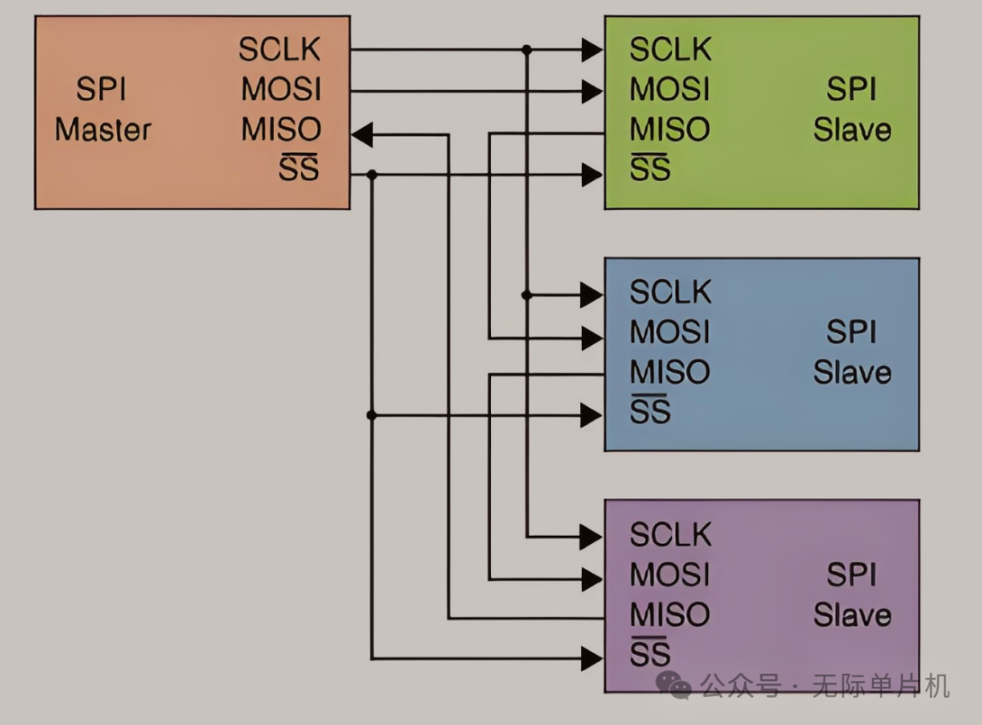
○SPI: The standard four-wire system (MOSI, MISO, SCLK, CS) sometimes requires additional interrupt/ready signals. It occupies more pins than UART. More critically, SPI operates on a master-slave structure, usually with the microcontroller as the Master controlling multiple Slave devices.
If you want to use a PC to debug the microcontroller via SPI:
▪Does the PC need to act as the Master? Then the microcontroller must be the Slave, which may conflict with its role in controlling other SPI Slaves in the system.
▪Does the PC act as a Slave? Then the microcontroller Master must actively initiate read/write to the PC, making the timing and logic quite strange.
▪Listening to the bus with the PC? Possible, but requires a dedicated SPI protocol analyzer or an adapter configured to listen mode, and what you see is raw data flow, which is not easy to read directly.
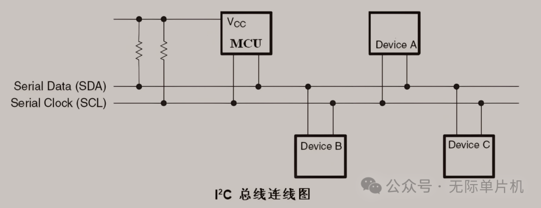
○I2C: Two-wire system (SDA, SCL) plus GND.
It seems simple, but:
▪Requires pull-up resistors.
▪Multi-master/multi-slave bus: All devices are connected on the same bus, distinguished by addresses, and debugging information must be packaged into I2C transactions, including addresses, read/write bits, etc., adding complexity.
▪Bus Conflicts/Arbitration: If debugging information is sent while there is other normal communication on the bus (like reading/writing sensors), it can easily cause conflicts, interfere with normal business logic, or even lead to bus lock-up—this is a debugging “disaster scene”.
2.Protocol Complexity and Software Overhead: A Bit “Heavy”
○Clock Synchronization: Both SPI and I2C are synchronous protocols that require the Master to provide clock signals. This requires strict synchronization on the clock edge between the sender and receiver, increasing implementation complexity (although hardware usually handles this).
○Structured Data: These two protocols are more suitable for transmitting structured data packets or performing register-style access (address + data). Using them to transmit printf generated, variable-length, plain text debugging streams feels a bit like “using a sledgehammer to crack a nut” and “format mismatch”. You have to define your own transmission protocol: how to packetize? How to identify start and end? How to handle text?
○Master/Slave Logic: Software needs to handle master/slave roles, chip selection (SPI), address matching/ACK/NACK (I2C), timing control, etc., which is much more complex than UART’s “just send bytes” operation. To log, writing a bunch of SPI/I2C driver code while carefully managing bus states yields a low return on investment.
3.PC Interface and Toolchain
○Dedicated Adapters: To communicate directly with the microcontroller’s SPI/I2C interface, you need a dedicated USB to SPI/I2C adapter (such as modules based on FTDI FT2232H/FT4232H, CH341A, etc.). These adapters are more expensive than USB to serial modules and are not as widely used.
○Lack of Standard Terminal Software: There is no universal software like PuTTY that can directly “open SPI/I2C ports” to view text. You need to use software that comes with the adapter, third-party software, or write your own host software to communicate with the microcontroller via SPI/I2C and parse custom debugging data formats. This greatly increases the preparation work and complexity of debugging.
4.Intrusiveness and Risk
○Shared Bus: This is one of the most critical issues.
In many systems, the SPI and I2C buses are already connected to critical peripherals (such as Flash memory, sensors, displays, etc.).
If you attempt to insert debugging information on these buses that are currently being used by applications, it is akin to cutting into a highway, which can easily:
▪Disrupt the timing of normal peripheral communications.
▪Cause data conflicts or errors.
▪Lead to abnormal system functions or even crashes.
○The purpose of debugging is to find problems, not to introduce new ones. Overlaying debugging streams on busy SPI/I2C buses carries too much risk.
3. Are There Exceptions? SPI/I2C Debugging “Guest Appearances”
That said, nothing is absolute. In certain specific scenarios, SPI or I2C may also be used for debugging purposes, but typically not as a replacement for UART for general printf output:
1.Debugging SPI/I2C Itself: When you suspect there are issues with SPI or I2C communication, you might use a logic analyzer to capture waveforms on the bus, or use dedicated SPI/I2C debuggers/adapters to actively interact with devices on the bus, but this is considered “diagnosing the bus”, not “outputting program logs through the bus”.
2.Severely Resource-Constrained: If a system is so pin-constrained that it cannot spare UART pins, or if UART has already been occupied by other core functions, engineers may be “forced” to attempt to implement a very rudimentary debugging output mechanism on some free SPI/I2C channel. But this is definitely a last resort, and the pain level is known only to those who have experienced it.
3.Specific Debugging Protocols: Some advanced debugging systems or on-chip debugging architectures may utilize SPI/I2C interfaces as physical channels to transmit highly structured debugging data or commands (for example, accessing internal registers or memory).
However, this usually requires specialized debugging hardware (such as J-Link, ST-Link, etc. emulators) and accompanying software (such as GDB, IDE debugging interfaces) to parse, and is not what we typically understand as “printing logs”. For instance, some chips’ debugging interfaces may repurpose I2C pins.
Conclusion: Specialization in Their Fields, UART is Irreplaceable
Returning to the initial question: why does embedded debugging favor UART and not use SPI/I2C?
The answer is clear: It is determined by the essential needs of debugging tasks and the characteristics of each interface.
Core Requirement of Debugging: To obtain streaming information about program execution status (mainly text logs) in the most cost-effective, least intrusive, and most convenient way, and possibly perform simple interactive control.
UART’s Characteristics: Simple hardware, lightweight protocol, asynchronous byte stream, perfectly fitting the PC ecosystem, just meets all the above requirements. It was born for this “coarse but extremely effective” debugging method.
SPI/I2C’s Characteristics: Optimized for connecting peripherals and transmitting structured data, features like synchronization, master-slave, and bus sharing, while advantages in their respective fields, become obstacles in general debugging scenarios, bringing complexity, risk, and inconvenience.
Therefore, it is not that SPI and I2C are not excellent, but rather that they operate on a different “track” than UART. In the embedded debugging track, UART, with its unparalleled “simplicity, usability, universality, and low risk” characteristics, has become the de facto standard and the most trusted “old friend” of engineers.
Next time you skillfully connect a USB to serial module, open PuTTY, and watch the scrolling debugging information on the screen, take a moment to appreciate UART, this unassuming yet outstanding “behind-the-scenes hero”! It may not be fast or flashy, but it always tells you the “truth” of the code world in the most direct way when you need it.
Choosing UART for debugging is not because it is “just okay”, but because it is “truly suitable”!
end