This article introduces the LED chaser experiment based on the 51 microcontroller, covering the following main content:
Experiment Objective: Master the basic usage of Proteus simulation software and Keil C51 programming, understand the minimum system configuration of the 51 microcontroller, and the principle of the LED chaser.
Hardware Design: Construct a minimum system using the AT89C51 microcontroller (including the crystal oscillator circuit and reset circuit), drive 8 LEDs through port P0, using a current-sourcing connection, and add pull-up resistors.
Software Implementation: Control the LED chaser display through C51 programming, including the design of a delay function (1ms reference) and port control logic.
Key Knowledge: Detailed explanation of the three main components of the minimum system of the microcontroller (main control, crystal oscillator, reset circuit), as well as the calculation method for the LED interface circuit.
Development Environment: Use Proteus 9.0 for circuit simulation and Keil 4 for program development.
This experiment can serve as an introductory learning project for the 51 microcontroller, helping to understand basic concepts such as I/O port control and timing design.
1. Teaching Objectives:
1. Understand and become familiar with the usage of Proteus.2. Learn the basic principles of the 51 microcontroller.3. Learn the operation mode of the LED chaser.4. Familiarize with C51 programming.
2. Preparations Before Class:
1. Prepare a computer.2. Download and install Proteus 9.0 software. (For installation tutorial, follow the WeChat public account at the bottom of this article and reply with 0005)3. Download and install Keil 5 C51 software. (For installation tutorial, follow the WeChat public account at the bottom of this article and reply with 0007)PS: This tutorial uses Proteus 9.0 and KEIL 5 C51
3. Hardware Circuit Design:
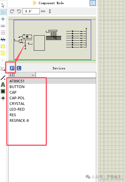
1. Component Selection
Open the PROTEUS software, click the icon below 【P】, and sequentially select 【AT89C51】, 【BUTTON】, 【CAP】………
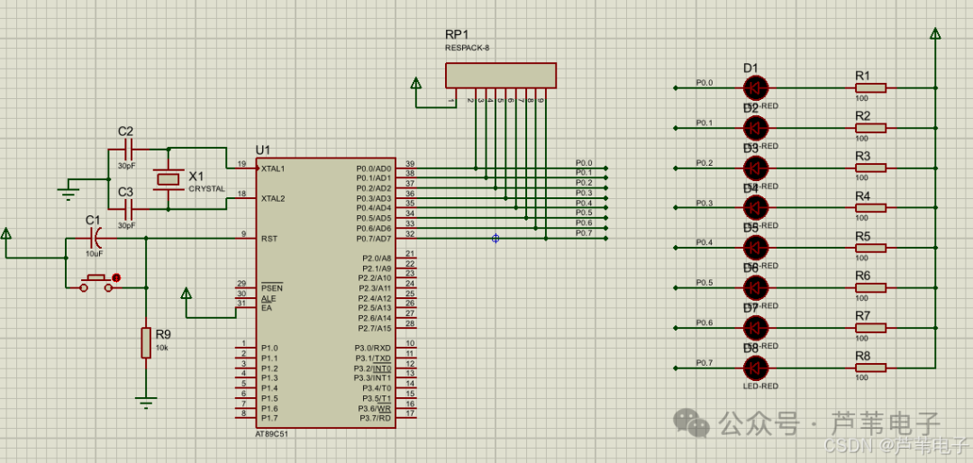
2. Build the Circuit
After a long time, it will eventually look like the image below:
2.1 Introduction to the Minimum System of the Microcontroller
The minimum system of the microcontroller consists of three main parts. The first part is the main circuit of the microcontroller, with the main component being the AT89C51 microcontroller, which has a total of 40 pins. The second part is the reset circuit, mainly composed of resistors, buttons, and capacitors. The third part is the crystal oscillator circuit, mainly composed of capacitors and a crystal oscillator, used to generate the crystal frequency.
2.1.1 AT89C51 Microcontroller The AT89C51 is a low-voltage, high-performance CMOS 8-bit microprocessor produced by Atmel, belonging to the MCS-51 series of compatible microcontrollers. Its core feature is the integration of a multifunctional 8-bit CPU with a flash programmable erasable read-only memory (FPEROM) on a single chip, providing a highly flexible and cost-effective solution for embedded control systems, widely used in industrial control, smart homes, electronic instruments, and other fields. As a classic 8-bit microcontroller, the AT89C51 has become the preferred choice for embedded development due to its high cost-performance ratio, strong compatibility, and rich peripheral resources.
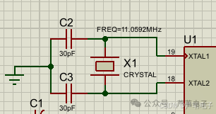
2.1.2 Crystal Oscillator Circuit The crystal oscillator circuit consists of capacitors C2, C3, and crystal X1. The capacitors mainly stabilize the frequency and enable quick oscillation, with capacitance values ranging from 5 to 30pF, with a typical value of 30pF. In this experiment, the capacitance values are all 30pF, one end connected to the crystal Y1 and the other end connected to the ground of the power supply. The crystal Y1 is mainly used to generate the crystal frequency, which should be less than 12 MHz, with typical values of 6MHz, 12MHz, and 11.0592MHz, among which 11.0592MHz is the most commonly used. In this experiment, the crystal frequency used is 11.0592MHz. The input end of the crystal oscillator circuit is connected to the XTAL1 pin of the microcontroller, and the output end is connected to the XTAL2 pin of the microcontroller. When the crystal oscillator circuit is powered on, it will generate oscillation.
2.1.3 Reset Circuit The reset circuit is an important part of the AT89C51 microcontroller system, with the core function of restoring the microcontroller to its initial state under specific conditions, ensuring that the system starts running from a known initial configuration. Depending on the triggering mechanism, reset methods can be divided into the following three categories:1) Power-on Reset: Automatically triggers a reset at the moment the circuit is powered on, relying on the transient signals generated during the rise of the power supply voltage to achieve initialization.2) Manual Reset: Controlled by an external button, when the button is pressed and held for at least 2 machine cycles (approximately 2μs at a 12MHz main frequency), the reset signal takes effect.3) Automatic Reset: Automatically triggered based on program logic or the state of external circuits (such as watchdog timer overflow), suitable for system exception recovery scenarios.
The requirements for the reset signal are:1) Level Standard: The reset pin (RST) must receive a high level input, while a low level is invalid.2) Duration: The minimum pulse width is 2 machine cycles, with the specific duration related to the system clock frequency (e.g., at a 12MHz clock, it must be ≥2μs).3) Pin Characteristics: The RST pin has no internal pull-up resistor and requires an external circuit to provide stable high-level drive. A typical circuit structure is the RC reset circuit: composed of resistor R9 (10kΩ) and capacitor C1 (10μF) in series, during power-on, the capacitor charging process keeps the RST pin at a high level for about 10ms, meeting the reset timing requirements. The button reset circuit is connected in parallel with the reset button on the RC circuit, which directly pulls the RST pin to a high level when pressed, and the capacitor discharges to restore low level when released.

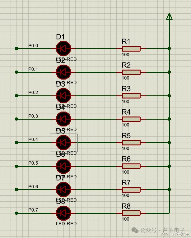
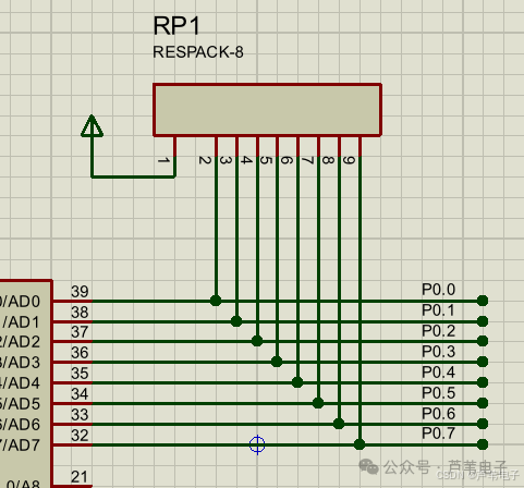
2.2 Introduction to the LED Interface Circuit
I/O Port Selection: This design uses port P0 (P0.0~P0.7) to connect 8 LEDs’ cathodes, using a current-sourcing connection method (to introduce the need for a pull-up resistor when using port P0, thereby expanding everyone’s knowledge).LED and Current-Limiting Resistor: Each LED anode is connected in series with a current-limiting resistor (recommended between 470Ω and 2kΩ) to port P1 pins. When the microcontroller pin outputs a low level, current flows through the LED and resistor to form a loop, lighting the LED; when it outputs a high level, the LED turns off. 1) Hardware Parameter MatchingCurrent-Limiting Resistor Calculation: Based on the LED forward voltage drop (approximately 1.8~2.2V) and operating current (10~20mA), using the formula R =(Vcc-Vled) /Iled, for example: under a 5V power supply, the current-limiting resistor R=(5V-2V)/10mA=300Ω, but in practice, a 1k resistor is often chosen to leave some margin. In the Proteus simulation, the current limit is small, so to increase the brightness of the LED during simulation, a 100Ω current-limiting resistor is used. 2) Port Driving Capability: The maximum current-sourcing capability of each pin on port P0 is 10mA, with a total current not exceeding 26mA.
PS:In Proteus, the P0 port of the 51 microcontroller requires a pull-up resistor.(1) Reason: The P0 port of the 51 microcontroller is an open-drain structure, which means it has no internal pull-up resistor (while P1, P2, and P3 ports have internal pull-up resistors). The open-drain structure means that when the P0 port is used as a general output port, if it outputs a high level (1), the internal transistor is turned off, and the P0 port pin is in a “floating” state, unable to stably output a high level (the voltage will fluctuate with the external circuit). Only after connecting an external pull-up resistor can the P0 port output a high level, allowing current to flow through the pull-up resistor to the power supply (VCC), stabilizing the pin at a high level (approximately equal to VCC voltage). In practice, a 10K pull-up resistor is often used for the P0 port.
4. Program Design:
1. Header Files and Macro Definitions
#include<reg52.h>
#include "intrins.h"
#define uchar unsigned char
#define uint  unsigned int
1.1 Header Files
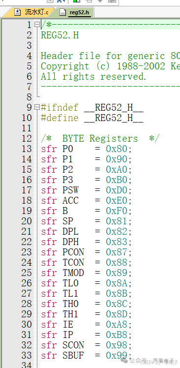
#include is used to include header files, this program includes two header files: reg52.h and intrins.h.1) Introduction to reg52.h Header File reg52.h is a commonly used standard header file in C language development for the 51 microcontroller, its core function is to define the internal special function registers (SFR) and bit operation symbols of the microcontroller, allowing developers to write control programs using intuitive symbols (such as P1, TCON, etc.) without directly manipulating low-level hardware addresses, simplifying the development process and improving code readability.
Key Functions of reg52.h Header File
Definition of Special Function Registers (SFR)In the header file, all addresses of the internal special function registers of the microcontroller are defined using the sfr keyword, for example:
sfr P0 = 0x80; (P0 port register address)sfr TCON = 0x88; (Timer control register address)sfr SCON = 0x98; (Serial port control register address)These definitions allow developers to directly use statements like P0 = 0xFF; to operate hardware, rather than memorizing hexadecimal addresses like 0x80.
Definition of Bit Operation SymbolsFor bits that can be addressed in registers, the header file defines bit operation symbols using the sbit keyword, for example:
sbit TF1 = 0x8F; (Timer T1 overflow flag bit)sbit TR0 = 0x8C; (Timer T0 run control bit)With these definitions, one can directly use statements like TF1 = 0; to operate individual bits without needing to control them indirectly through bitwise operations.
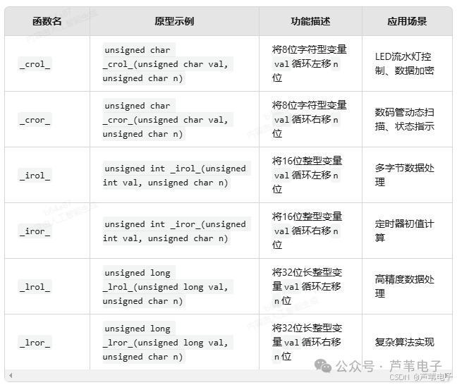
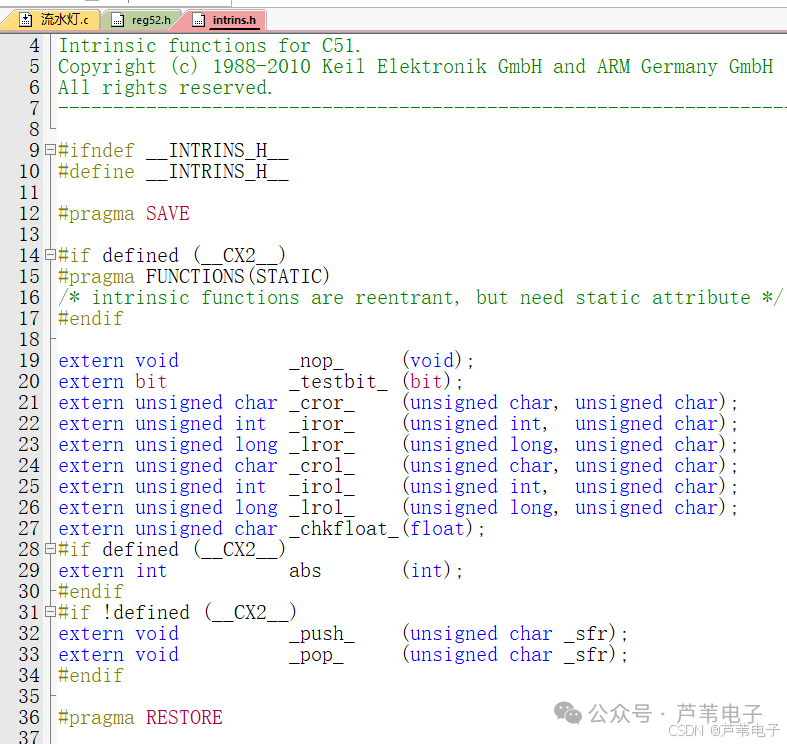
2) Introduction to intrins.h Header File intrins.h is a C language header file specifically designed for the 8051 series microcontrollers (such as AT89C51), its core function is to encapsulate assembly-level instructions into C functions, providing direct support for low-level hardware operations of the microcontroller, simplifying programming implementations for bit operations, circular shifts, delay control, and other scenarios. This header file is usually included when functions like circular shifts, no-operation (NOP), or bit testing and clearing are needed, serving as a bridge between the C51 compiler and the 8051 hardware instruction set. Core function classification and description of the intrins.h header fileCircular Shift FunctionsThis type of function implements bitwise circular movement of data, supporting different data types (char, int, long), with high and low bits connecting end-to-end after shifting, without unsigned extension.
No Operation Function _nop_()Function: Generates a NOP assembly instruction, with an execution time of 1 machine cycle (e.g., under a 12MHz crystal, it takes 1μs), used for precise delays or timing control.Characteristics: The C51 compiler directly embeds the NOP instruction, with no function call overhead, making it suitable as a delay benchmark or for hardware timing matching (such as generating start signals for I²C bus).Bit Testing and Clearing Function _testbit_()Prototype: bit testbit(bit bitvar)Function: Tests the value of the specified bit variable bitvar, returning 1 and automatically clearing that bit if it is 1, or returning 0 if it is 0; equivalent to the 8051 assembly instruction JBC (test bit and jump to clear).Application: External interrupt flag detection, clearing state after key debounce, etc., avoiding manual clearing operations.
1.2 Macro Definitions
#define is a very basic and commonly used macro definition, its purpose is to create short aliases for data types, mainly to simplify code writing and improve readability. This program uses #define to create a short alias for the unsigned char data type as uchar; and for the unsigned int data type as uint.
2. Delay Function
To allow viewers to see the flowing effect of the lights, a delay function has been added.
/*****************************************************************
*Function: Delay approximately 1ms at 11.0592MHz  Just remember the fixed format
*****************************************************************/
void delay1ms(uint time)        //@11.0592MHz
{
    uchar i, j;
while(time--)
    {
        _nop_();
        i = 2;
        j = 199;
        do
        {
            while (--j);
        } while (--i);
    }
}
3. Main Program
/*****************************************************************
*Main Program
*****************************************************************/
void main(void)
{
    uchar i,temp;    //Introduce variables i and temp
    while(1)
    {
        // Left LED chaser
              temp= 0xFE; // In binary: 11111110
                for (i = 0; i < 8; i++)
                {
                    P0 = temp;
                    delay1ms(500);
                    temp = _crol_(temp,1);    // Circular left shift function, defined in intrins.h header file
                }
                // Right LED chaser
                temp= 0x7F; // In binary: 01111111
                for (i = 0; i < 8; i++)
                {
                    P0 = temp;
                    delay1ms(500);
                    temp = _cror_(temp,1);    // Circular right shift function, defined in intrins.h header file    01111111   10111111
                }
    }
}
uchar: A simplified unsigned char (8-bit unsigned variable) through macro definition.i: A counter for the for loop (controls the steps of the LED chaser, a total of 8 steps corresponding to 8 LEDs).temp: Stores the state data of the LEDs (8-bit binary number, each bit corresponds to the on/off state of an LED, 0 means on, 1 means off).The typical structure of a microcontroller program places all logic that needs to run continuously in while(1).The initial state temp = 0xFE;In binary: 11111110, corresponding to the 8 pins of port P0 (P0.0P0.7);The lowest bit (P0.0) is 0 → the connected LED is on;the other bits (P0.1P0.7) are 1 → corresponding LEDs are off.At this point, the rightmost LED (connected to P0.0) is lit.Circular left shift _crol_(temp, 1):Each time, the 8-bit binary number of temp is circularly shifted left by 1 bit (the highest bit moves to the lowest bit), for example:First left shift: 11111110 → 11111101 (P0.1 corresponding LED is on);Second left shift: 11111101 → 11111011 (P0.2 corresponding LED is on);… and so on, until after 8 shifts, the lit LED moves from the right to the left.delay1ms(500):Delays for 500 milliseconds (0.5 seconds), allowing each LED’s lit state to be maintained for a period, so that the human eye can see the flowing effect.The initial state temp = 0x7F:In binary: 01111111, the highest bit (P0.7) is 0 → the leftmost LED (connected to P0.7) is on, while the others are off.Circular right shift _cror_(temp, 1):Each time, the 8-bit binary number of temp is circularly shifted right by 1 bit (the lowest bit moves to the highest bit), for example:First right shift: 01111111 → 10111111 (P0.6 corresponding LED is on);Second right shift: 10111111 → 11011111 (P0.5 corresponding LED is on);… and so on, after 8 shifts, the lit LED moves from the left to the right.
5. Obtain Materials:
Follow the WeChat public account below and reply with 009