System Overview
This design implements a simple speed measurement system using the AT89C51 microcontroller, which detects the speed of rotating objects through a Hall sensor and displays it in real-time on an LCD1602. With appropriate modifications, it can serve as a bicycle odometer, car engine speedometer, or vehicle mileage meter. The system includes the following main components:
-
AT89C51 microcontroller as the main controller
-
LCD1602 display module for real-time speed display
-
Hall sensor (simulated using a 555 oscillator) for pulse detection
-
Proteus simulation environment for validation
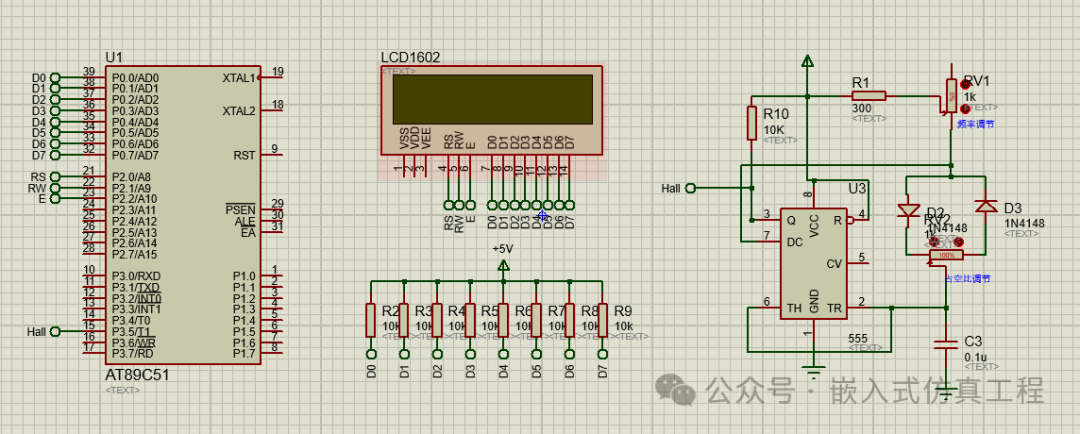
Hardware Connections
LCD1602 Connection
-
P0.0-P0.7 → LCD D0-D7 (data bus)
-
P2.0 → LCD RS (register select)
-
P2.1 → LCD RW (read/write select)
-
P2.2 → LCD E (enable signal)
Sensor Connection
-
P3.5 → Hall sensor input/555 oscillator input
555 Oscillator Circuit (Simulating Hall Sensor)
The 555 timer is configured in astable multivibrator mode to simulate the pulse output of a Hall sensor in Proteus. Typical connection method:
-
Power VCC
-
Ground GND
-
Output connected to P3.5
-
The output frequency can be changed by adjusting the resistors and capacitors, allowing for modification of the maximum and minimum frequencies to simulate actual pulse input frequencies.
Software Design
Main Program Flow
-
Initialize LCD
-
Initialize timer/counter
-
Enter main loop
-
Calculate speed
-
Update LCD display
-
Delay for an appropriate time
Key Code Implementation
void main(void)
{
LcdInitiate();
TMOD=0x51;
TH0=19453/256;
TL0=19453%256;
EA=1;
ET0=1;
TR0=1;
count=0;
display_sym();
display_val(0);
display_unit();
while(1)
{
TR1=1;
TH1=0;
TL1=0;
flag=0;
while(flag==0)
;
Val=(TH1*256+TL1)*60/16;
display_val(Val);
}
}
Proteus Simulation Setup
-
Create a new project, select AT89C51 microcontroller
-
Add LCD1602 component
-
Add 555 timer circuit to simulate Hall pulses
-
Connect the pins of each component
-
Load the compiled HEX file
-
Run the simulation, adjust the 555 oscillation frequency, and observe the LCD display
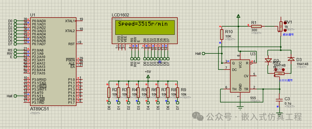
Parameter Calculation and Adjustment
-
Speed calculation formula:
<span>Speed = (Pulse Count × Wheel Circumference) / Time</span>
-
Assuming a wheel circumference of 0.5 meters, the pulse count per second is the speed value (m/s)
Timer settings:
-
Timer 0: Interrupt once every 50ms, 20 times for 1 second
-
Timer 1: Used for external pulse counting
Precautions
-
In practical applications, calculation parameters need to be adjusted based on the actual parameters of the Hall sensor and the characteristics of the measured object
-
In Proteus simulation, the frequency of the 555 oscillator can be changed by adjusting the resistor and capacitor values to simulate speed
-
LCD initialization requires sufficient delay time
-
Actual speed display may require adding filtering algorithms to reduce fluctuations
Extended Features
-
Add key settings function (e.g., wheel circumference setting)
-
Add maximum speed and average speed calculations
-
Add overspeed alarm function
-
Use more precise timing methods to improve measurement accuracy
Through the above design, a simple speed measurement system based on AT89C51 can be realized and validated in Proteus simulation. In practical applications, relevant parameters need to be adjusted according to specific hardware and measurement requirements.