PID Controller, also known as Proportional-Integral-Derivative Controller, is a type of feedback control system and mechanism used to control the regulation process of a system to reach the desired setpoint. It is a widely used control algorithm in industrial plants. The algorithm continuously calculates the error signal based on the difference between the desired setpoint and the measured process variable (temperature, pressure, etc.), and then adjusts the control output accordingly to minimize the error and bring the process variable closer to the setpoint. This article demonstrates how to use Arduino as an automatic PID controller to control the temperature of an oven.
In this article, you will learn the following:
· Explore using a K-type thermocouple and AD8495 module to use Arduino as a PID controller for temperature control.
· Understand how to implement a PID (Proportional-Integral-Derivative) controller using the popular Arduino platform, and delve into tuning parameters such as Proportional Gain (Kp), Integral Gain (Ki), and Derivative Gain (Kd) for optimal temperature control.
· Learn how to read and scale the setpoint from a potentiometer input, and how to convert the temperature input from the thermocouple to Celsius using appropriate calibration coefficients.
· Witness a practical demonstration of how the PID controller calculates the output and uses PWM (Pulse Width Modulation) to send it to the oven to regulate the temperature, while monitoring and displaying the temperature and setpoint on an LCD screen and serial monitor.
· Additionally, learn how to dynamically adjust the tuning parameters of the PID controller through the serial monitor and observe the direct impact of gain changes on temperature control performance. Whether you are a beginner or an experienced Arduino enthusiast, this video will provide you with valuable insights into implementing PID control in temperature applications.
· Arduino Temperature PID Controller Circuit Diagram and Working Principle
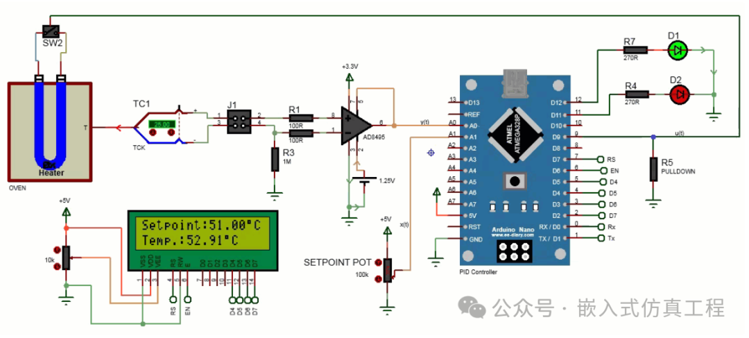
· Here, Arduino is programmed as a PID controller to control the temperature of the oven. The following diagram shows the circuit diagram of the oven temperature controller using the Arduino PID controller.
Set the desired temperature using a potentiometer connected to analog pin A1, for example, 50 degrees. This is called the setpoint. Use the thermocouple to measure the temperature of the oven. The voltage from the thermocouple is very small, so an AD8495 thermocouple amplifier is used to amplify the thermocouple signal. The output of the AD8495 IC is connected to the Arduino’s analog pin A0. Thus, the Arduino reads the temperature and compares it with the setpoint temperature. The Arduino executes the PID algorithm, calculating the error and using the proportional constant (Kp), integral constant (Ki), and derivative constant (Kd) to compute the output value to reach the setpoint temperature. The output is sent to a digital switch that controls the oven temperature. The oven temperature is controlled by a PWM signal from Arduino pin 9. The values of Kp, Ki, and Kd can be provided from the serial monitor. The LCD screen displays the set temperature and the current temperature. If the temperature reaches the set range, a green LED lights up; otherwise, a red LED remains lit. The LED flashes to visually indicate that the desired temperature has been reached.
Arduino PID Controller Code
Below is the Arduino code for the PID (Proportional-Integral-Derivative) controller that controls the temperature using a K-type thermocouple and AD8495 thermocouple amplifier module. This code reads the temperature from the thermocouple, compares it with the set value obtained from the potentiometer, and then adjusts the oven output using the PID control algorithm. It also displays the temperature and set value on the LCD screen and controls two LEDs (green LED and red LED) to indicate whether the temperature is within the desired range.
// Arduino PID Controller for
// Arduino PID Controller for temperature control with K-type Thermocouple and AD8495
// By www.ee-diary.com
// library to drive the 16×1 LCD display
#include
// library for PID
#include
// initialize the LCD library with the numbers of the interface pins
LiquidCrystal lcd(7, 6, 5, 4, 3, 2);
float gain = 0.00488;
float ref = 1.25313;
const int GreenLED = 12;
const int RedLED = 11;
const int thermocouplePin = A0;
const int potPin = A1; // Potentiometer input pin
const int ovenPin = 9; // LED output pin
// Tuning parameters
float Kp = 0; // Proportional gain
float Ki = 0.5; // Integral gain
float Kd = 0; // Differential gain
// Record the set point as well as the controller input(y) and output(u)
double Setpoint, y, u;
// Create a controller that is linked to the specified Input, Ouput and Setpoint
PID myPID(&y, &u, &Setpoint, Kp, Ki, Kd, DIRECT);
const int sampleRate = 1; // Time interval of the PID control
void setup(){
//setup serial at 9600 bps
Serial.begin(9600);
//LCD setup
lcd.begin(16, 2);
//setup LEDs as output
pinMode(GreenLED, OUTPUT);
pinMode(RedLED, OUTPUT);
myPID.SetMode(AUTOMATIC); // Turn on the PID control
myPID.SetSampleTime(sampleRate); // Assign the sample rate of the control
}
void loop(){
//——-PID Controller——-
Setpoint = map(analogRead(potPin), 0, 1023, 0, 255); // read and scale the set point
// read the temperature input convert to Celsius degree
y = (double(analogRead(thermocouplePin)) * gain – ref)/0.005;
myPID.Compute(); // Calculates the PID output at a specified sample time
analogWrite(ovenPin, u); // Send output to oven
//Turn on LEDs according to whether the temperature is within range
if(y <= 53 && y >= 47){
digitalWrite(RedLED, LOW);
digitalWrite(GreenLED, HIGH);
}
else{
digitalWrite(RedLED, HIGH);
digitalWrite(GreenLED, LOW);
}
//Display on Serial Monitor
Serial.print(“Temperature: “);
Serial.print(y);
Serial.print(“°C, “);
Serial.print(“Setpoint:”);
Serial.print(Setpoint);
Serial.print(“, “);
Serial.print(“Output:”);
Serial.println(u);
// The tuning parameters can be retrieved by the Arduino from the serial monitor: eg: 0,0.5,0 with Ki set to 0.5.
// Commas are ignored by the Serial.parseFloat() command
if (Serial.available() > 0){
for (int i = 0; i < 4; i++){
switch(i){
case 0:
Kp = Serial.parseFloat();
break;
case 1:
Ki = Serial.parseFloat();
break;
case 2:
Kd = Serial.parseFloat();
break;
case 3:
for (int j = Serial.available(); j == 0; j–){
Serial.read();
}
break;
}
Serial.print(” Kp,Ki,Kd = “); // Display the new parameters
Serial.print(Kp);
Serial.print(“,”);
Serial.print(Ki);
Serial.print(“,”);
Serial.print(Kd);
Serial.println();
myPID.SetTunings(Kp, Ki, Kd); // Set the tuning of the PID loop
}
//Display on LCD
lcd.setCursor(0, 0);
lcd.print(“Setpoint:”);
lcd.print(Setpoint);
lcd.write(0xdf); // to display °
lcd.print(“C”);
lcd.setCursor(0, 1);
lcd.print(“Temp.: “);
lcd.print(y);
lcd.write(0xdf); // to display °
lcd.print(“C”);
delay(500); // wait a bit
}
The code works as follows:
1.Library Inclusion: The code includes two libraries – LiquidCrystal.h for controlling the LCD display and PID_v1.h for implementing the PID algorithm.
2.Variable Declaration: The code declares various variables to store gains, reference voltage, LED pin numbers, thermocouple input, potentiometer input, and oven output. Additionally, it declares variables for the PID controller tuning parameters (Kp, Ki, Kd), as well as variables to store the PID algorithm setpoint, controller input (y), and controller output (u).
3.Setup Function: The setup() function is called only once when the Arduino starts. This function initializes serial communication at 9600 bps, sets up the LCD display, configures the LED pins as outputs, sets the PID mode to automatic, and specifies the sample rate for the PID control.
4.Loop Function: The loop() function is repeatedly called after the setup() function. It implements the main logic of the PID controller.
5.PID Control: The code reads the setpoint from the potentiometer, scales it to a range of 0-255, and stores it in the Setpoint variable. It reads the thermocouple input, converts it to Celsius using the gain and reference voltage values, and stores it in the y variable. Then, it executes the PID algorithm using the myPID.Compute() function, which calculates the PID output (u) based on the setpoint, input (y), and previously set tuning parameters (Kp, Ki, Kd). The PID output is written to the oven output pin using the analogWrite() function.
6.LED Control: The code uses the digitalWrite() function to check if the temperature is within the desired range (between 47°C and 53°C). If it is, the GreenLED is turned on; if not, the RedLED is turned on.
7.Serial Communication: The code uses Serial.print() and Serial.println() functions to display the temperature, setpoint, and PID output values on the serial monitor. It also listens for incoming data on the serial monitor to update the tuning parameters of the PID controller. If new tuning parameters are received, they are parsed using the Serial.parseFloat() function and the PID tuning is updated using the myPID.SetTunings() function.
8.LCD Display: The code uses the lcd.print() function to update the current setpoint and temperature values on the LCD display. It also uses the lcd.write() function to write the degree symbol (°) to the display.
9.Delay: The code adds a 500-millisecond delay using the delay() function to avoid rapid updates of the PID control loop.
The loop() function continuously repeats these steps, utilizing the K-type thermocouple and AD8495 amplifier module to achieve PID control of temperature, providing feedback through the LCD display, LEDs, and serial monitor.