Recently, I have seen many popular articles using 50-ohm coaxial cables to measure power supply ripple, various styles, and impressive content. I finally took the time to research related articles and would like to share some personal recommendations for measuring ripple & noise with an oscilloscope in my work.When testing power supply waveforms, we often observe fluctuations. Some say this is ripple, while others say it is noise.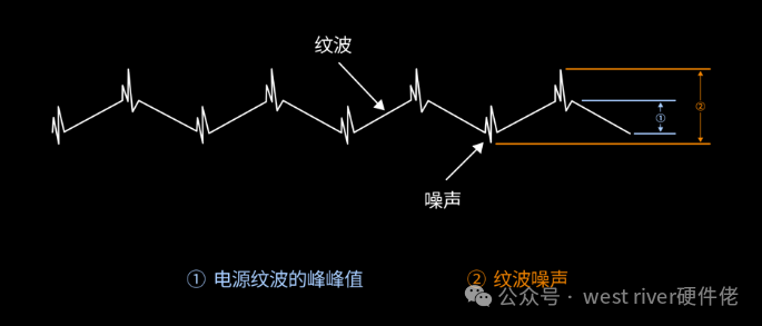 First, let’s clarify the two concepts of ripple and noise:Here, I borrow the description from deepseek:
Ripple
Definition
Ripple refers to the periodic fluctuation component superimposed on the DC voltage output of the power supply, mainly caused by the switching actions within the power supply (such as switch-mode power supplies) or inadequate rectification and filtering (such as linear power supplies).
-
Frequency Range: Typically related to the switching frequency of the power supply (e.g., tens of kHz to MHz) or the input AC frequency (e.g., 50Hz/60Hz mains frequency).
-
Waveform Characteristics: Exhibits regular periodic fluctuations (e.g., sine wave, sawtooth wave).
Causes
-
Switching Power Supply: Rapid switching of MOSFETs leads to residual fluctuations after LC filtering.
-
Linear Power Supply: Incomplete filtering of the AC component after rectification (e.g., insufficient capacitance of the filter capacitor).
-
Load Variation: Dynamic loads cause slight oscillations during feedback loop adjustments.
Noise
Definition
Noise is the non-periodic, random high-frequency interference signal present in the circuit, which may originate from internal or external sources.
-
Frequency Range: Wide bandwidth (from a few Hz to GHz), with no obvious regularity.
-
Waveform Characteristics: Random spurious signals (e.g., white noise, spike pulses).
Causes
-
Internal Noise: Thermal noise from semiconductor devices (Johnson noise), shot noise, 1/f noise, etc.
-
External Interference: Electromagnetic radiation (EMI), ground coupling, switching transients (e.g., relay actions).
-
Power Supply Noise: High-frequency switching noise from DC-DC converters (e.g., ringing, parasitic oscillation).
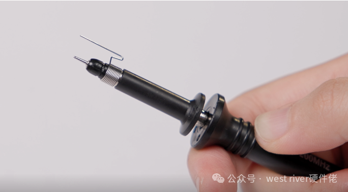
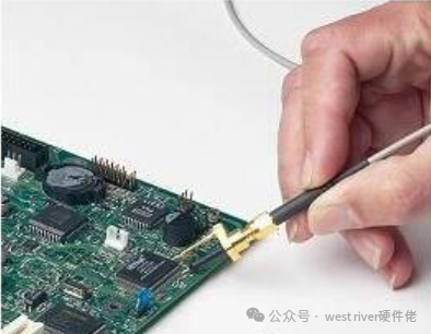
The mainstream methods for measuring ripple currently are using a ground probe and a 50-ohm coaxial cable:
Of course, there is a third method, but I do not recommend it.
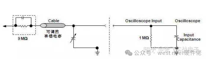
 Before discussing measurement methods, let’s first talk about the internal circuit of the oscilloscope probe to the oscilloscope channel.Compensated high-impedance passive probes are the most commonly used passive probes, and the probes that come standard with most oscilloscopes are of this type.
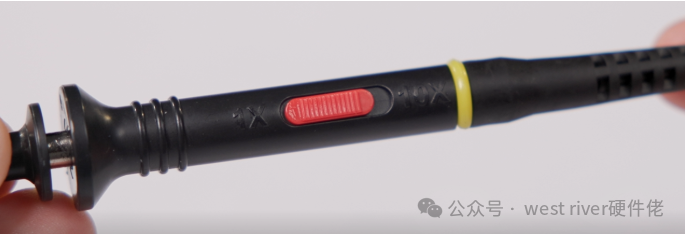
 Using this probe with a ground probeBandwidth:Limited to 20MHz,
Channel Coupling: AC Coupling
Probe Attenuation: Set to 1X because the amplitude of power supply ripple is generally small. If set to 10:1, the signal will be attenuated tenfold entering the instrument, and then amplified tenfold through digital computation, which will amplify a lot of noise, leading to a higher measured value of ripple.
Input Impedance: Set to 1MΩ
Voltage Range:20mV/div (this can be adjusted flexibly according to the actual size of the measured ripple)
At large ranges, the oscilloscope’s inherent noise will be amplified. For example, if the basic range of the oscilloscope is 10mV/div, the inherent noise is 500uV. When the range is changed to 100mV/div, the oscilloscope input will add a 10:1 attenuator, and when displayed, the signal will be amplified tenfold, resulting in an inherent noise of 5mV.
Using50-ohm coaxial cable
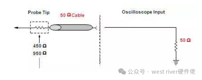 Bandwidth:Limited to 20MHz
Channel Coupling: AC Coupling
(Some oscilloscopes do not support 50-ohm impedance in AC mode, so setting to DC coupling is also considered acceptable, but it is recommended to use a DC blocking capacitor)
The schematic of the DC blocking capacitor: The capacitance added here can be 100nF or 10uF, and I personally believe both can be connected in parallel.
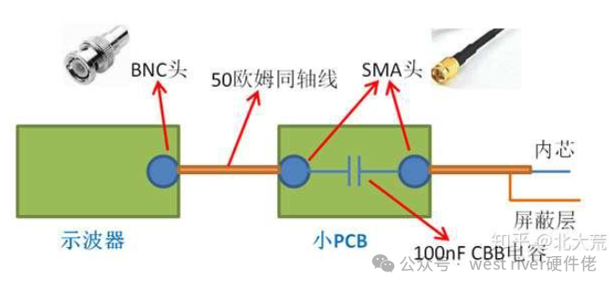
Probe Attenuation: Set to 1X
Input Impedance: Set to 50Ω
Voltage Range:20mV/div (this can be adjusted flexibly according to the actual size of the measured ripple)
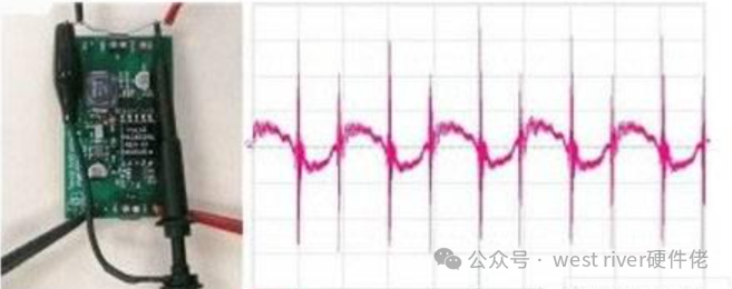
The following images show the ripple measured with a 50-ohm coaxial cable with bandwidth limited to 20MHz and limited to 100MHz.
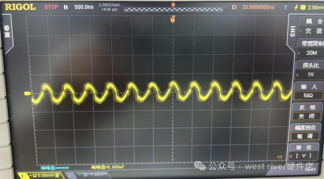
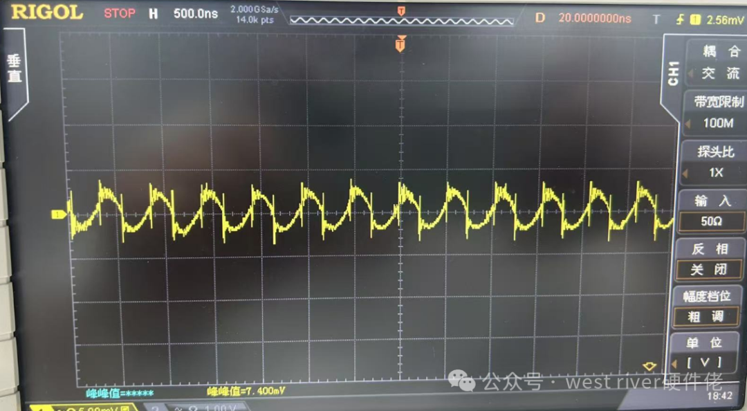
It can be seen that the 100MHz image introduces noise.
The reason for limiting the bandwidth to 20MHz when measuring ripple is primarily to avoid high-frequency noise from digital circuits affecting the measurement of ripple, ensuring measurement accuracy as much as possible.
As mentioned earlier, the frequency range of ripple is usually related to the switching frequency of the power supply (e.g., tens of kHz to MHz) or the input AC frequency (e.g., 50Hz/60Hz mains frequency).If measuring noise, the bandwidth limit of the oscilloscope can be turned off.