Power supply ripple testing is a crucial parameter in power quality detection, but accurately measuring power supply ripple has become a challenge for engineers. How can we overcome this problem? In fact, after searching for it thousands of times, the solution is right there in front of us.
 Because a DC regulated power supply is generally formed by rectifying, filtering, and stabilizing an AC power source, it inevitably contains some AC components in the DC voltage. This superimposed AC component on the stable DC voltage is referred to as ripple.
1. Incorrect Ripple Testing
By connecting a 3.3V power signal to the ZDS2024 Plus oscilloscope and using the X10 probe setting, we measured the power supply ripple. After clicking on [Auto Setup], we adjusted the horizontal time base, vertical range, and vertical offset to obtain the waveform shown in Figure 1.
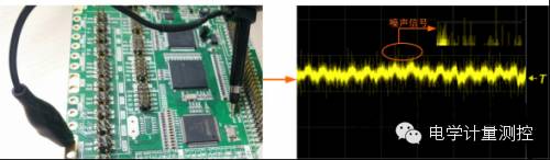
Figure 1 Incorrect Ripple Measurement Method
As shown in the figure, the measured waveform is mixed with a lot of noise and interference, making it impossible to clearly observe the ripple and accurately measure its value. Many engineers encounter this situation because they have not mastered the correct ripple measurement method.
2. Correct Power Supply Ripple Testing Method
1. First, select the appropriate probe setting. If the voltage is relatively high or if there are high bandwidth requirements, you can use the X10 setting; under normal circumstances, it is recommended to use the X1 setting to avoid unnecessary noise attenuation affecting the ripple measurement.
2. Since ripple is an AC component, the “channel coupling” method should be set to “AC” to limit the input of DC signals, as shown in Figure 2.
3. You can appropriately use the “bandwidth limit” function by selecting a “20MHz” bandwidth limit to filter out unnecessary high-frequency noise, as shown in Figure 2.
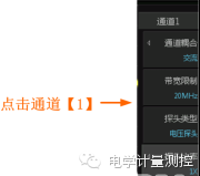
Figure 2 Channel Interface Parameter Settings
4. Additionally, it is crucial to avoid interference from electromagnetic radiation and other sources, so during measurement, it is recommended to use a “ground spring” for grounding to avoid unnecessary interference from long grounding wires.
5. The trigger method can use edge triggering, with the trigger mode set to either Auto or Normal.
6. Adjust the horizontal time base, vertical range, and vertical offset appropriately to display the waveform signal in the center of the screen with good effect.
The captured ripple is shown in Figure 3.
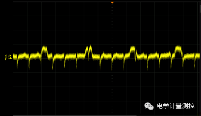
Figure 3 Correctly Captured Ripple
From Figure 3, it can be seen that the correct ripple measurement method can clearly capture the normal ripple, reducing the impact of unnecessary noise and interference, resulting in a clean ripple. With this foundation, power supply ripple measurements can be conducted more accurately, leading to a more precise assessment of power supply quality.
Ripple testing is generally expressed in peak-to-peak values. You can use the [measure] function for automatic measurement, as shown in the screenshot of the ZDS2000 series oscilloscope, which supports 51 types of true parameter measurement statistics based on full storage depth to measure ripple parameters, or you can use the “one-key cursor” for manual measurement, as shown in Figure 4.
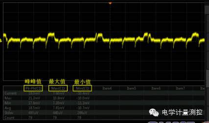
Figure 4 Ripple Measurement Data
3. Measurement Result Analysis
From the measurement, it can be seen that the peak-to-peak value of this power supply ripple is 18mV. Intel specifies in the ATX12V specification that the +12V output ripple peak-to-peak value must not exceed 120mV, and the +3.3V and +5V ripple peak-to-peak values must not exceed 50mV. The smaller the ripple, the higher the power supply quality.