Multisim is a simulation tool developed by National Instruments (NI) based on Windows, suitable for the design of board-level analog/digital circuit boards. It includes graphical input for circuit schematics and circuit hardware description language input methods, with rich simulation and analysis capabilities. Engineers can use Multisim to interactively build circuit schematics and simulate circuits.
01
Role of Multisim
Traditional electronic circuit design development usually requires making a prototype board or conducting simulation tests on a breadboard.
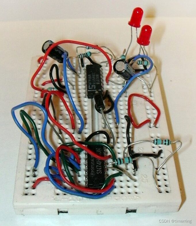
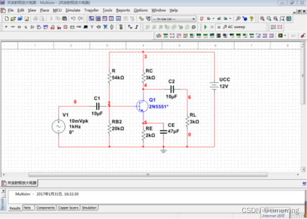
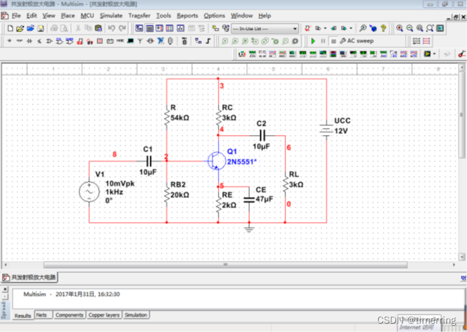
Engineers can use the virtual electronic devices and instruments provided by Multisim to build, simulate, and debug circuits, thereby reducing the design costs and R&D cycle of circuits.
02
Interface of Multisim 14.0
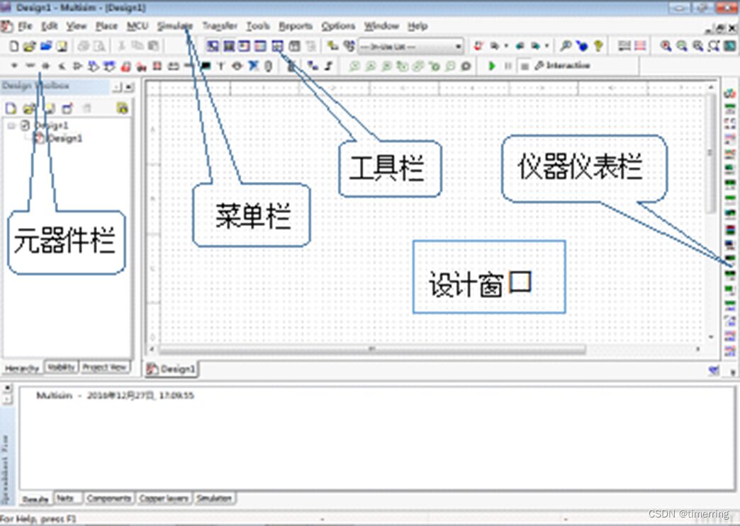
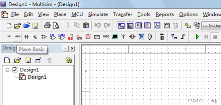
1. Design Window
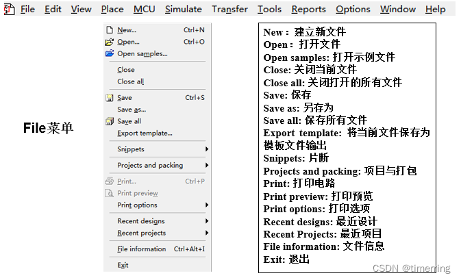
2. Menu Bar
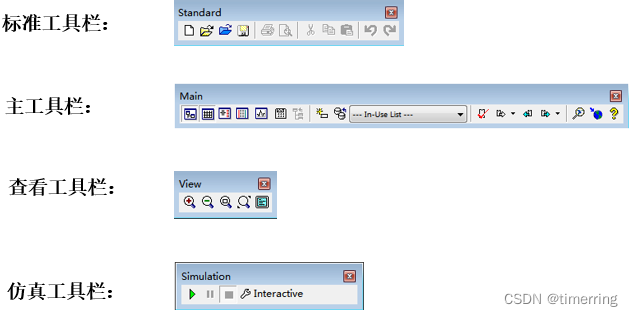
3. Toolbar
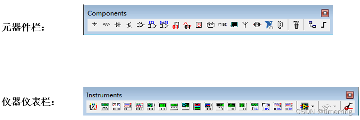
4. Component Bar and Instrument Bar
03
Components
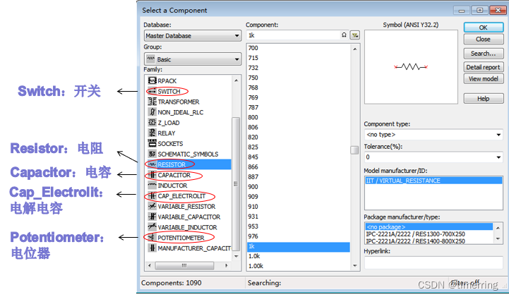
5. Components – Basic Components
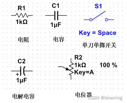
Resistors, potentiometers, capacitors, electrolytic capacitors, switches, etc.
(1) Click “Place Basic” to place basic components.
(2) Select the appropriate component and parameters.
(3) At this point, the “Select a Component” window closes, left-click to place the component icon at the appropriate position on the circuit diagram.
(4) The “Select a Component” window will pop up again; if no more components need to be placed, close the pop-up window.
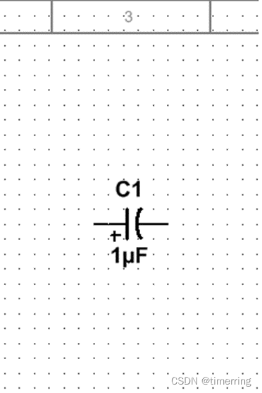
6. Components – Electrolytic Capacitor
An electrolytic capacitor is a capacitor with “polarity”. When using, the positive pole of the electrolytic capacitor should be connected to the ” + ” pole of the power supply, and the negative pole should be connected to the ” – ” pole of the power supply.
7. Components – Switch
Select SPST (Single Pole Single Throw Switch)
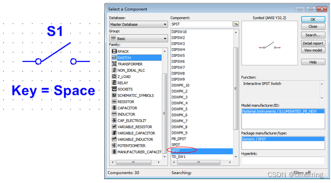
Using the mouse or shortcut keys, you can toggle the switch between “on” and “off” states.
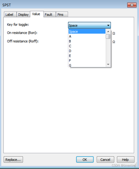
Switch – Modify Shortcut Key
Double-click the switch icon, and the “SPST” window pops up.
Click the “Value” tab.
Select a shortcut key from the dropdown menu after “Key for toggle”.
Click “OK”.
8. Components – Potentiometer
By adjusting the potentiometer, you can change the resistance between the sliding terminal and the two fixed terminals.

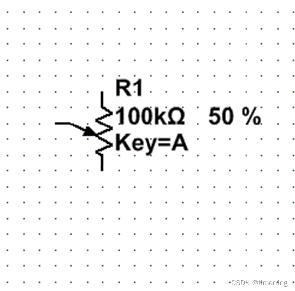
Adjusting the Potentiometer – Method One
Hover the mouse over the potentiometer to see the slider shown on the right. Drag the slider with the mouse to change the resistance value between the sliding terminal and the two fixed terminals.
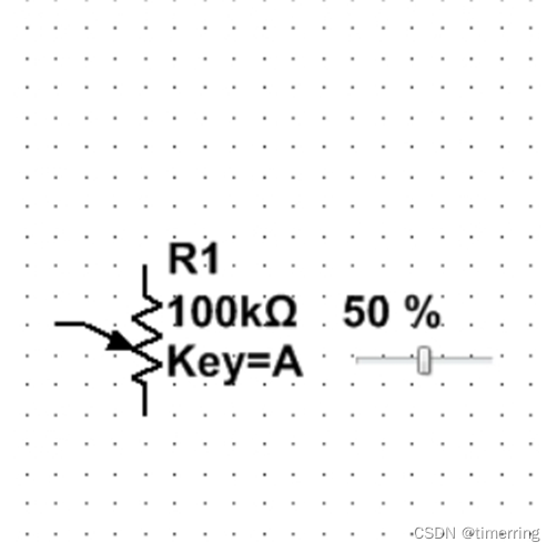
Adjusting the Potentiometer – Method Two
If the potentiometer icon shows “Key=A”, it means pressing the “A” key can increase the resistance value between the sliding terminal and the lower fixed terminal by a fixed increment percentage of the total resistance; pressing the “A” key + Shift key can decrease this percentage.
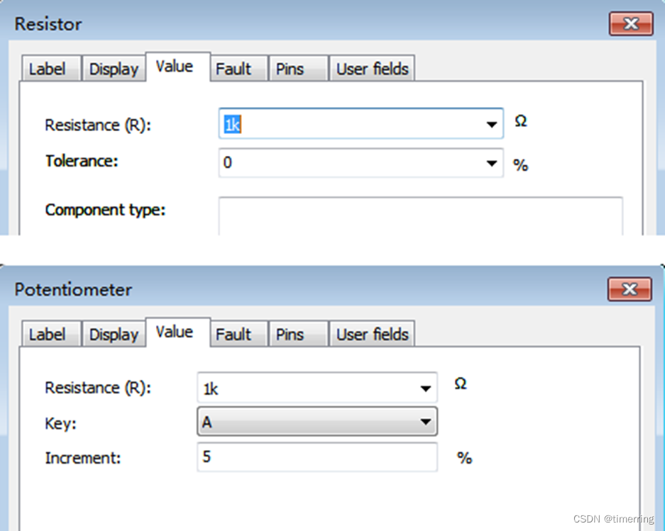
Adjusting the Potentiometer – Modify Adjustment Precision
Double-click the potentiometer icon, click the “Value” tab in the pop-up “Potentiometer” window, fill in the new adjustment precision after “Increment:”, and finally click “OK”.
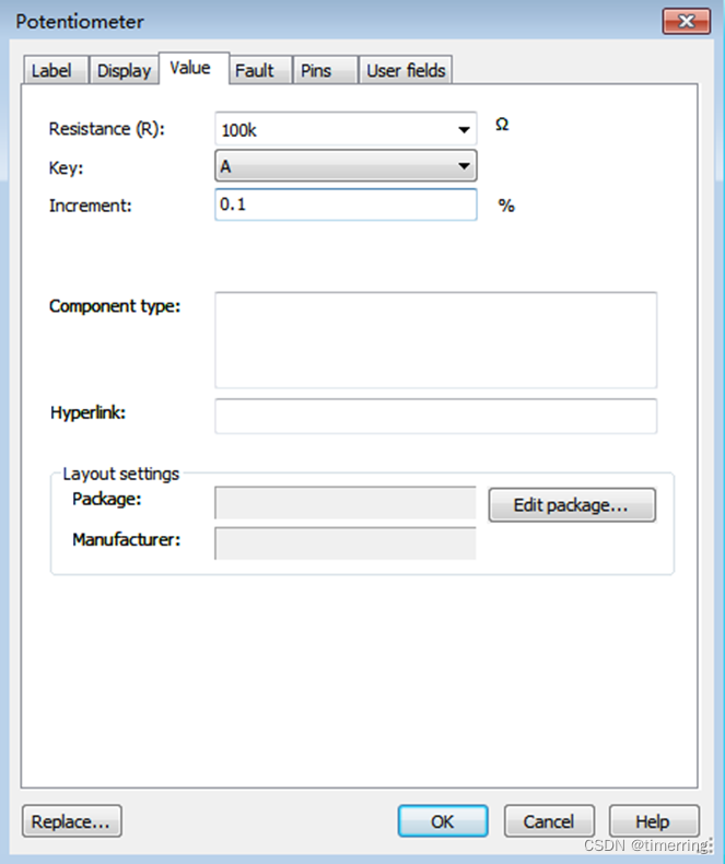
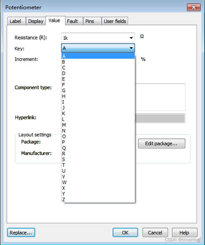
Potentiometer – Modify Shortcut Key
Double-click the potentiometer icon, click the “Value” tab in the pop-up “Potentiometer” window, select a shortcut key from the dropdown menu after “Key:”, and finally click “OK”.
Modify Resistance and Potentiometer Values
Double-click the component icon, click the “Value” tab in the pop-up window, fill in the new resistance value after “Resistance(R):”, and finally click “OK”.
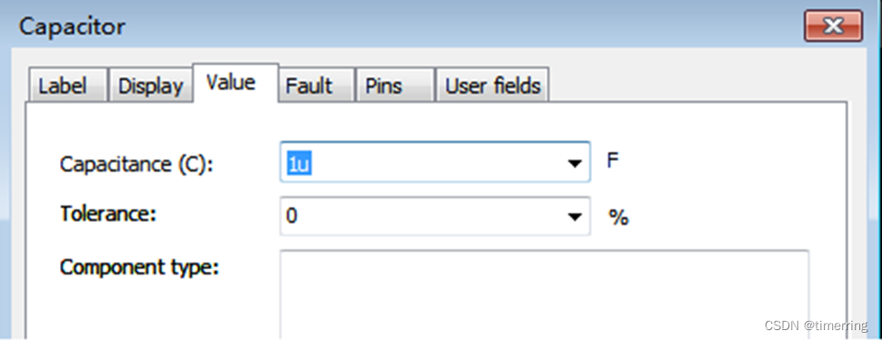
Modify Capacitance and Electrolytic Capacitor Values
Double-click the component icon, click the “Value” tab in the pop-up window, fill in the new capacitance value after “Capacitance(C):”, and finally click “OK”.
Multisim is a simulation tool developed by National Instruments (NI) based on Windows, suitable for the design of board-level analog/digital circuit boards. It includes graphical input for circuit schematics and circuit hardware description language input methods, with rich simulation and analysis capabilities. Engineers can use Multisim to interactively build circuit schematics and simulate circuits.

Image Editing | Chen Yulong
Review | Zhang Hongyan
Final Review | Chen Hao