What functions can be achieved by combining the ESP32 screen module with an LED light board? The project presented today only requires a swipe on the 4.3-inch touchscreen, and the neural network can instantly understand your handwriting and display the number you wrote on an 8×8 LED light board. Isn’t it amazing? Let’s see how 【Mr.Wolf】 achieved this!

Project Introduction
This project uses the CrowPanel ESP32 Display 4.3-inch HMI development board in conjunction with the Hardhe LED dot matrix light board for soldering training, along with the ESP32-S2-MINI-1 development board as an auxiliary. It utilizes Micropython and lvgl to achieve handwritten digit recognition and display. The lvgl library is used to collect handwritten digits, and a multilayer perceptron neural network is employed to recognize the collected handwritten digits. Finally, the recognized results are sent to the LED light board device for display via TCP communication.
Hardware Introduction
1. ESP32 Display 4.3-Inch Module
The CrowPanel ESP32 Display 4.3-inch HMI development board is a powerful HMI touchscreen with a 480×272 resolution LCD display and an IC NV3047 driver board, utilizing resistive touch technology.
This development board uses the ESP32-S3-WROOM-1-N4R2 module as the main control processor, featuring a dual-core 32-bit LX7 processor, integrated WiFi and Bluetooth wireless capabilities, with a maximum frequency of 240MHz, providing strong performance and multifunctional applications. Additionally, the board reserves a TF card slot, various peripheral interfaces, USB interface, speaker interface, battery interface, etc., offering more expansion possibilities.
2. Hardhe LED Dot Matrix Light Board for Soldering Training
This LED dot matrix light board has 64 monochrome LEDs arranged in an 8×8 grid, along with 64 0603 packaged resistors, two series-parallel conversion SOIC-16 packaged 74HC595D, two 0603 packaged power decoupling capacitors, two 5-pin connectors, eight NPN transistors 9013, and sixteen 0603 packaged resistors, used to drive the LED array, providing the necessary current for lighting each row of 8 LEDs.
3. ESP32-S2-MINI-1 Development Board
This module features the ESP32-S2-MINI-1 module, a 2.4 GHz WiFi module built with the ESP32-S2 series chip, Xtensa® single-core 32-bit LX7 microprocessor, 37 GPIOs, and rich peripherals, with an onboard PCB antenna.
In addition, this development board integrates a USB TYPE-C interface, two buttons, a power indicator, a user LED, and two rows of 10-pin headers to expose important IOs. It can be powered via USB or through the header with 3.3V.
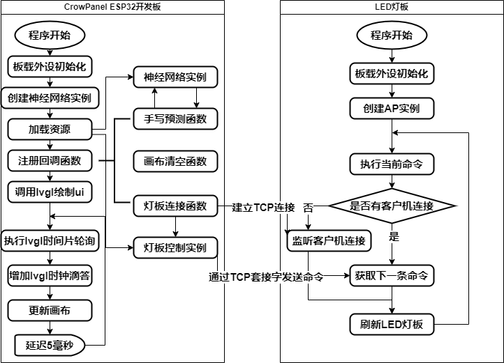
Solution Block Diagram and Design Ideas
1. Solution Block Diagram
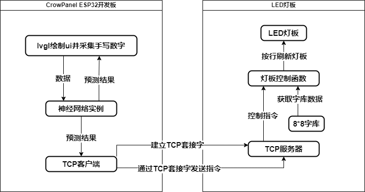
2. Project Design Ideas
-
Create a UI using Micropython and lvgl to collect handwritten digits and provide feedback of the recognition results on the screen.
-
Run a simple MLP neural network on the CrowPanel ESP32 Display 4.3-inch HMI development board to recognize the collected handwritten digits.
-
Send the recognized results to the LED light board device for display via TCP socket.
-
Run a TCP server on the LED light board device to establish a communication connection with the main development board.
-
Draw the received characters on the LED light board in a row-scanning manner.
Function Demonstration
The implemented function is the collection and recognition of handwritten digits, with the recognized results sent to the LED light board for display.
Below are images and brief descriptions:
01
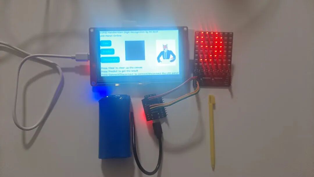
This image provides an overview of the project, divided into the CrowPanel ESP32 display board section and the LED light board section. The LED light board can operate as an independent IoT device, powered by a 5V lithium battery pack (the blue device in the image is the lithium battery); the display section is powered via USB from a computer.
02
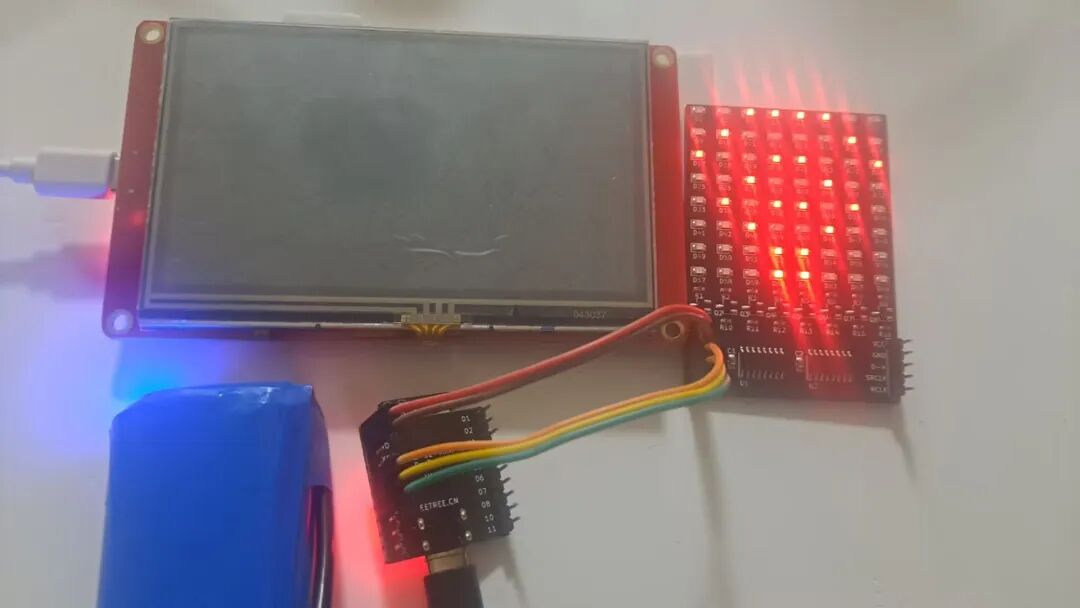
This image shows the state when only the LED light board is powered on. The WiFi signal-like pattern on the light board (there are four frames in total, only one frame is shown here) indicates that the TCP server on the light board has been activated and is waiting for a client connection.
03
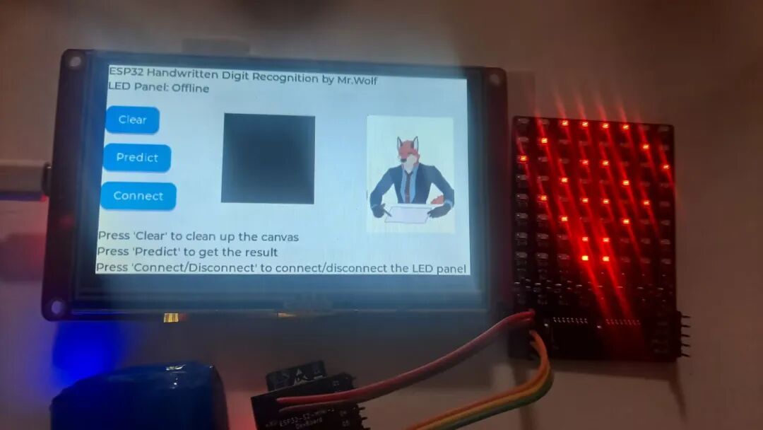
This image shows the interface after the display screen is powered on. At this point, the CrowPanel ESP32 development board has not yet established a connection with the LED light board, so the screen displays the light board as offline (“Offline”). The light board still shows the WiFi symbol animation waiting for a client connection.
04
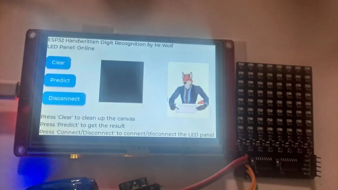
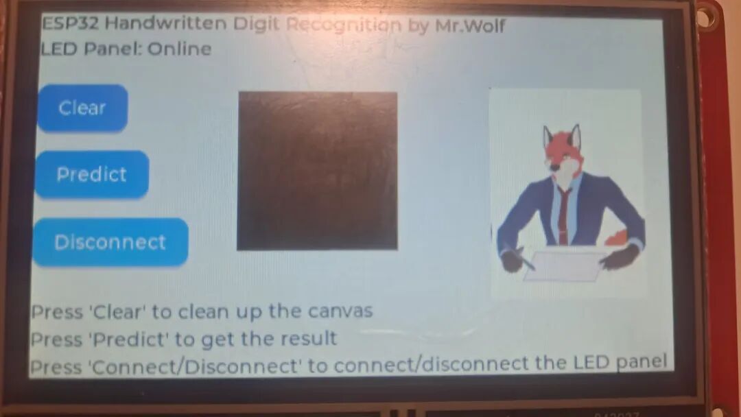
This image shows the state after clicking the “Connect” button, establishing a connection between the CrowPanel ESP32 development board and the LED light board. At this point, the screen displays the LED status as online (“Online”); simultaneously, the WiFi signal-like pattern on the light board disappears, and the screen clears, waiting for client instructions.
05
This image is a close-up of the CrowPanel ESP32 development board screen. The first line at the top of the screen shows the project name, the second line indicates the LED light board status; the three buttons on the left side of the middle of the screen, from top to bottom, are Clear (“Clear”) – to clear the content on the canvas, Predict (“Predict”) – to make a prediction on the content written on the canvas, Disconnect (“Disconnect”, when not connected to the LED light board it shows “Connect”) – to disconnect from the LED light board (when not connected, it attempts to connect to the LED light board). The black area in the middle of the screen is the handwriting canvas for writing digits, and the small fox on the right side of the middle of the screen informs the user of the predicted number after clicking the predict button through a text box, enhancing the interactivity and fun of this project; the three lines of text at the bottom of the screen are help documentation.
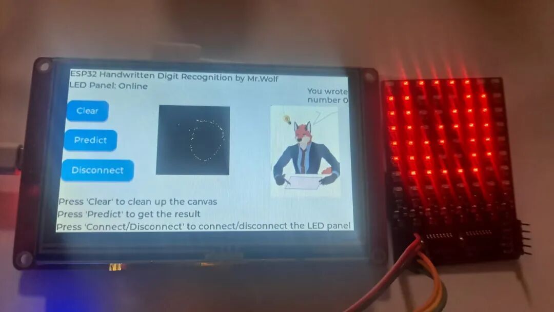
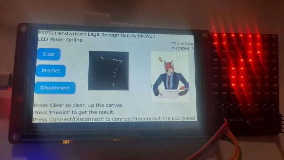
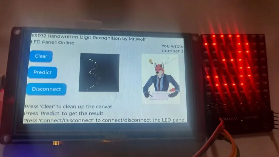
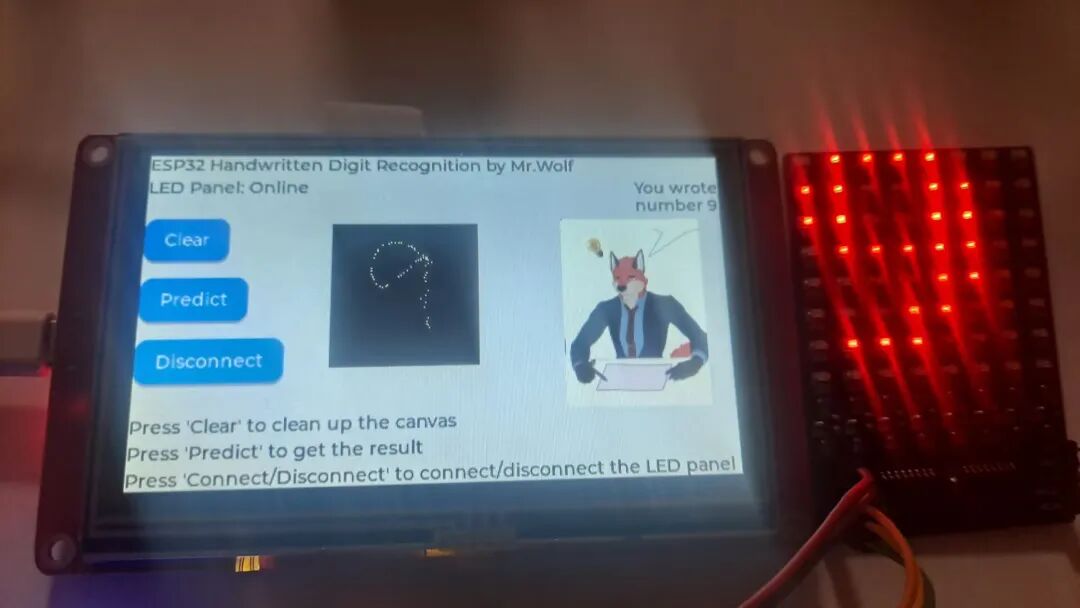
The above image shows the recognition results for handwritten digits 0-9, proving the project’s success in handwritten digit recognition. In addition to the display results on the light board, the small fox on the screen also provides the predicted results in the upper right corner text, making the project lively.
Software Introduction
1. Software Flowchart
For detailed software introduction, please visit Eetree to view and download the attached code for experimentation. The project has been open-sourced on Eetree: https://www.eetree.cn/project/detail/3917.
Challenges Encountered and Solutions
1. Neural Network Usage Issues
Problem Description:
Most existing neural networks that support microcontrollers require development in C/C++. Very few neural networks that support Micropython require proprietary hardware or need to be pre-compiled into the firmware, and the official firmware provided does not include such libraries; moreover, this development board has only 512KB of RAM, which is resource-constrained.
Solution:
I adopted a self-written neural network model that only uses Micropython’s general libraries, making it easy to port; furthermore, if the referenced Micropython libraries are replaced with Python standard libraries, this neural network can also be ported to a computer, allowing for training the neural network using the computer’s high computing power, and then transferring the trained weight files to the Micropython device.
This neural network consists of only 215 lines, and the weight file for handwritten digit recognition is only 54KB. The neural network part includes complete training methods, prediction methods, model evaluation methods, data shuffling algorithms, activation functions and their derivatives, as well as methods for saving and loading weights, with the training method also including error backpropagation.
2. Memory Allocation Issues
Problem Description:
Due to the high overhead of the lvgl + neural network system, memory consumption is rapid, possibly due to a small memory allocation-related issue within Micropython, leading to the data related to screen drawing potentially being corrupted after running for a period, causing the screen to freeze and not refresh normally (but without triggering any catchable errors).
Temporary Solution:
This issue only causes the screen to freeze; other parts can still function normally, and users can still use other features (including collecting handwritten digits, recognition, and controlling light board display, etc.). Users can press the reset button on the board at their convenience to restart and recover.
3. lvgl Canvas Issues
Problem Description:
Due to discrepancies between the lvgl library functions provided in the firmware and those used in mainstream online tutorials, it was impossible to use the indev to obtain touch coordinates as described in online tutorials.
Solution:
Directly use the get_touch from the xpt touch driver in the main loop to obtain the coordinates of touch events, first checking whether the coordinates are within the canvas, and then using the set_px method of the lvgl canvas to draw the touch event coordinates point by point on the canvas component.
Insights and Reflections
Through this experiment, I successfully implemented the handwritten recognition display task based on the CrowPanel ESP32 Display 4.3-inch HMI development board. Through this activity, I deeply learned the GUI development with Micropython + lvgl and the basic theories and development training of neural networks, accumulating valuable experience. I would also like to thank Hardhe Academy for providing me with this opportunity.
As for suggestions, I hope that if conditions allow, the onboard main control chip of the CrowPanel ESP32 Display 4.3-inch HMI development board can be upgraded from ESP32-S3-WROOM-1-N4R2 to ESP32-S3-WROOM-1-N16R8 to provide stronger performance and more possibilities for edge AI applications.
Future Prospects
Although this project has successfully implemented the handwritten recognition display task based on the CrowPanel ESP32 Display 4.3-inch HMI development board and achieved the expected indicators, there are still many areas for improvement and expansion:
-
The current multilayer perceptron neural network model for handwritten recognition is still not very stable, with accuracy fluctuating. In the future, I hope to collect more handwritten digit datasets for training to increase the robustness of this model.
-
Deeply investigate potential memory issues, find and fix vulnerabilities that may lead to the risk of screen freezing.
-
Expand the display font library and animations of the LED light board, and integrate other external devices with the CrowPanel ESP32 Display 4.3-inch HMI development board to build a more complete IoT system.
-
Add animations to the UI of the CrowPanel ESP32 Display 4.3-inch HMI development board and expand its functionality.
The project has been open-sourced on Eetree, and you can click “Read the original text” to check it out. What other creative patterns can the dot matrix light board recognize? Everyone is welcome to try!
“Hardhe Academy” LED board for soldering training (excluding microcontroller)

Click to read the original text to view the project