Comprehensive Resources for Primary School Science
Public Account: Primary School Science Network
| Micro Lesson Collection | Digital Textbooks | Teaching Materials and Lesson Plans |
| Selected Exam Papers | Special Grade Teachers | Qingdao Science |
| Su Education Edition Science | Science Experiments | Activity Manuals |
| Teaching Plans | Experiment Plans | Science Clubs |
| Experiment Videos | Mind Maps | Resource Collections |
| First Grade Resources | Second Grade Resources | Third Grade Resources |
| Fourth Grade Resources | Fifth Grade Resources | Sixth Grade Resources |
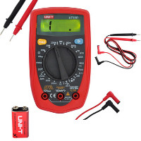
A multimeter, also known as a multifunction meter, three-in-one meter, or universal meter, is a versatile measuring instrument that can generally measure direct current, direct voltage, alternating voltage, resistance, and audio levels. Some can also measure alternating current, capacitance, inductance, and certain parameters of semiconductors (such as β).
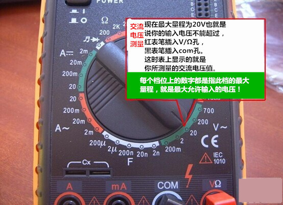
AC voltage measurement: As shown in Figure 1, the maximum range is 20V, which means your input voltage cannot exceed this. The red probe is inserted into the v/Ω hole, and the black probe is inserted into the com hole. The value displayed on the meter is the AC voltage you are measuring.
Digital measuring instruments have become mainstream because they offer high sensitivity, high accuracy, clear display, strong overload capacity, portability, and ease of use.

1. Structure of Multimeter (Model 500)
The multimeter consists of three main parts: the meter head, measurement circuit, and selector switch.
(1) Meter Head
It is a highly sensitive magnetic electric DC ammeter. The main performance indicators of the multimeter basically depend on the performance of the meter head. The sensitivity of the meter head refers to the value of the DC current flowing through the meter head when the pointer deflects to full scale; the smaller this value, the higher the sensitivity of the meter head. The higher the internal resistance when measuring voltage, the better the performance. The meter head has four scale lines, which function as follows: The first line (from top to bottom) is marked R or Ω, indicating resistance value, read when the selector switch is in the ohm range. The second line is marked ∽ and VA, indicating AC and DC voltage and DC current values, read when the selector switch is in AC or DC voltage or current mode, with ranges other than AC 10V. The third line is marked 10V, indicating the AC voltage value of 10V, read when the selector switch is in AC or DC voltage mode at the 10V range. The fourth line is marked dB, indicating audio level.
(2) Measurement Circuit
The measurement circuit is used to convert various measurements into suitable micro DC currents for the meter head. It consists of resistors, semiconductor components, and batteries.
It can convert various measurements (such as current, voltage, resistance, etc.) and different ranges into a certain limit of micro DC current for measurement by the meter head through a series of processing (such as rectification, shunting, voltage division, etc.).
(3) Selector Switch
The selector switch is used to select different measurement circuits to meet the requirements of various types and ranges of measurements. There are generally two selector switches, marked with different positions and ranges.
2. Symbol Meanings
(1) ∽ indicates AC and DC
(2) V-2.5KV 4000Ω/V indicates that the sensitivity for AC voltage and 2.5KV DC voltage is 4000Ω/V
(3) A-V-Ω indicates that it can measure current, voltage, and resistance
(4) 45-65-1000Hz indicates a frequency range below 1000Hz, with a standard power frequency range of 45-65Hz
(5) 2000Ω/V DC indicates that the sensitivity for the DC range is 2000Ω/V
The symbols on clamp meters and shaking meters are similar to the above symbols (others cannot be fully written due to symbol format issues).
3. Using the Multimeter
(1) Familiarize yourself with the meanings of the symbols on the dial and the main functions of each knob and selector switch.
(2) Perform a mechanical zero adjustment.
(3) Based on the type and size of the measurement, select the appropriate position and range on the selector switch and find the corresponding scale line.
(4) Choose the position for the probes.
(5) Measuring Voltage: When measuring voltage (or current), select the appropriate range. If a low range is used to measure a high voltage, there is a risk of burning the meter; if a high range is used to measure a low voltage, the pointer will deflect too little to read. The range should be selected to make the pointer deflect about 2/3 of the full scale. If the size of the voltage to be measured is not known beforehand, start with the highest range and gradually reduce to the appropriate range.
(a) Measuring AC Voltage: Set one selector switch to AC or DC voltage, and the other to the appropriate range for AC voltage. Connect the two probes in parallel with the circuit or load being measured.
(b) Measuring DC Voltage: Set one selector switch to AC or DC voltage, and the other to the appropriate range for DC voltage, ensuring the “+” probe (red probe) is connected to the high potential and the “-” probe (black probe) to the low potential, allowing current to flow from the “+” probe into the circuit and out from the “-” probe. If the probes are reversed, the meter head pointer will deflect in the opposite direction, risking bending the pointer.
(6) Measuring Current: When measuring DC current, set one selector switch to DC current and the other to the appropriate range from 50uA to 500mA. The selection of the current range and reading method is the same as for voltage. The circuit must be disconnected before measuring, and the multimeter must be connected in series with the circuit being measured, allowing current to flow from the red probe into the circuit and out from the black probe. If the multimeter is mistakenly connected in parallel with the load, the low internal resistance will cause a short circuit, damaging the instrument. The reading method is as follows:
Actual Value = Indicated Value × Range / Full Scale Deflection
(7) Measuring Resistance: When measuring resistance with a multimeter, follow these steps:
(a) Select the appropriate range. The ohm range scale is uneven, so the selection should make the pointer stop in the less dense part of the scale, ideally near the middle of the scale for more accurate readings. Generally, aim for the pointer to be between 1/3 and 2/3 of the scale.
(b) Perform ohm zero adjustment. Before measuring resistance, short the two probes together and adjust the “ohm (electrical) zero adjustment knob” so that the pointer points to the zero position just to the right of the ohm scale line. If the pointer cannot be adjusted to zero, it indicates insufficient battery voltage or internal issues with the instrument. Each time the range is changed, ohm zero adjustment should be performed again to ensure accurate measurements.
(c) Reading: The reading on the meter head multiplied by the range gives the measured resistance value.
(8) Precautions
(a) When measuring current or voltage, do not change the range while powered.
(b) When selecting a range, start from the large range and then select the smaller one, aiming to keep the measured value close to the range.
(c) Do not measure resistance while powered. When measuring resistance, the multimeter is powered by its internal battery, and measuring while powered is equivalent to connecting an additional power source, which may damage the meter head.
(d) When finished, set the selector switch to the maximum AC voltage range or the off position.
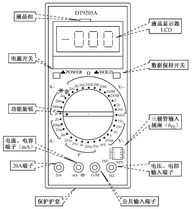
4. Digital Multimeter
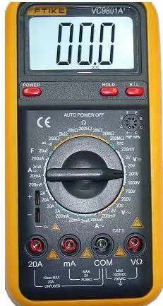
Currently, digital measuring instruments have become mainstream, with a trend to replace analog instruments. Compared to analog instruments, digital instruments offer higher sensitivity, higher accuracy, clearer display, stronger overload capacity, portability, and simpler use. Below, using the VC9802 digital multimeter as an example, we will briefly introduce its usage and precautions.
(1) Usage
a. Before use, carefully read the relevant user manual to familiarize yourself with the power switch, range switch, plug holes, and the functions of special sockets.
b. Set the power switch to the ON position.
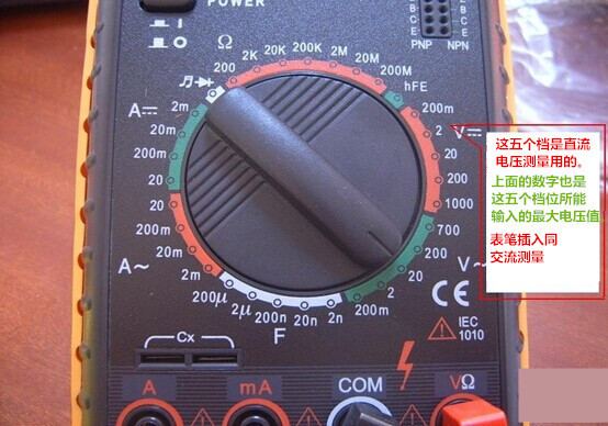
c. Measuring AC and DC voltage: Set the range switch to the appropriate range for DCV (direct current) or ACV (alternating current), insert the red probe into the V/Ω hole, the black probe into the COM hole, and connect the probes in parallel with the circuit being measured. The reading will be displayed.
d. Measuring AC and DC current: Set the range switch to the appropriate range for DCA (direct current) or ACA (alternating current), insert the red probe into the mA hole (for <200mA) or the 10A hole (for >200mA), the black probe into the COM hole, and connect the multimeter in series with the circuit being measured. When measuring DC, the digital multimeter will automatically display the polarity.
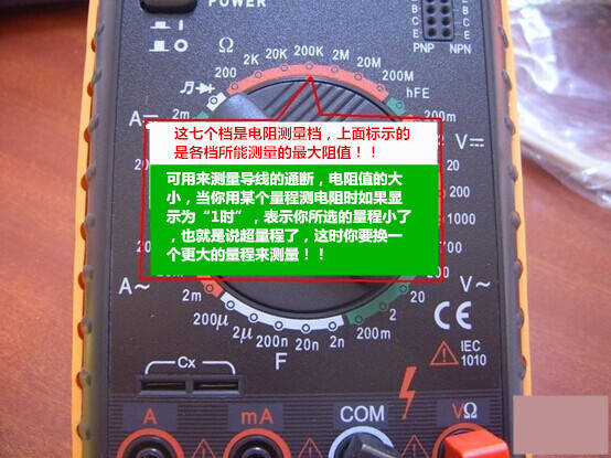
e. Measuring resistance: Set the range switch to the appropriate range for Ω, insert the red probe into the V/Ω hole, the black probe into the COM hole. If the measured resistance exceeds the maximum value of the selected range, the multimeter will display “1”; at this point, select a higher range. When measuring resistance, the red probe is positive, and the black probe is negative, which is the opposite of the analog multimeter. Therefore, when measuring polarized components like transistors or electrolytic capacitors, pay attention to the polarity of the probes.
(2) Precautions
a. If you cannot estimate the size of the voltage or current to be measured beforehand, first set it to the highest range and measure once, then gradually reduce the range to an appropriate position. When finished, set the range switch to the highest voltage range and turn off the power.
b. When at full range, the meter will only display the digit “1” at the highest position, with other positions disappearing; at this point, select a higher range.
c. When measuring voltage, connect the digital multimeter in parallel with the circuit being measured. When measuring current, connect it in series with the circuit being measured, and when measuring DC, polarity does not need to be considered.
d. If the AC voltage range is mistakenly used to measure DC voltage, or vice versa, the display will show “000” or the digits at the lower position will fluctuate.
e. Do not change the range when measuring high voltage (above 220V) or high current (above 0.5A) to prevent arcing and damage to the switch contacts.
f. When the display shows ” “, “BATT”, or “LOW BAT”, it indicates that the battery voltage is below the operating voltage.
5. Shake Meter
A shake meter, also known as an insulation resistance tester, is used to measure the insulation resistance and high resistance of the equipment being tested. It consists of a hand-cranked generator, a meter head, and three connection terminals (L: line terminal, E: ground terminal, G: shield terminal).
1) Selection Principles for Shake Meters
(1) Selection of rated voltage level. Generally, for equipment rated below 500V, select a shake meter rated at 500V or 1000V; for equipment rated above 500V, select a shake meter rated at 1000V-2500V.
(2) Selection of resistance range. The scale line on the shake meter has two small black dots, and the area between the dots is the accurate measurement area. Therefore, when selecting a meter, ensure that the insulation resistance value of the equipment being tested falls within the accurate measurement area.
2) Using the Shake Meter
(1) Calibration. Before measuring, perform an open circuit and short circuit test to check if the shake meter is functioning properly. Disconnect the two connection wires, crank the handle, and the pointer should point to “∞”; then short the two connection wires, and the pointer should point to “0”. If these conditions are met, the meter is good; otherwise, it should not be used.
(2) Disconnect the device and circuit to be tested, and discharge large capacitive devices.
(3) Select a shake meter with a voltage rating that matches the test.
(4) When measuring insulation resistance, generally only the “L” and “E” terminals are used. However, when measuring the insulation resistance of cables to ground or when leakage current is significant, the “G” terminal should be used, connecting it to the shielding layer or casing. After connecting the lines, turn the crank clockwise, starting slowly and then speeding up. When the speed reaches about 120 revolutions per minute (for model ZC-25), maintain a steady speed, read the value after one minute, and read while cranking without stopping.
(5) Discharge after reading. After taking the reading, keep cranking slowly while disconnecting the lines, then discharge the device being tested. The discharge method is to remove the ground wire used during measurement from the shake meter and short it to the device being tested (not the shake meter discharging).
3) Precautions
(1) Do not measure insulation resistance during thunderstorms or near high-voltage equipment; measurements should only be taken when the equipment is de-energized and free of induced voltage.
(2) During the shaking measurement process, no one should be working on the device being tested.
(3) The shake meter wires should not be twisted together; they should be separated.
(4) Before stopping the shake meter or before discharging the device being tested, do not touch it with your hands. When disconnecting the wires, do not touch the metal parts of the leads.
(5) After measuring, discharge large capacitive devices.
(6) Regularly verify its accuracy.
6. Clamp Meter
A clamp meter is an instrument used to measure the current of an electrical line while it is in operation, allowing current measurement without interrupting the power supply.
1) Structure and Principle
A clamp meter essentially consists of a current transformer, a clamp-shaped wrench, and a rectifying magnetic electric system with feedback.
2) Usage
(1) Perform mechanical zero adjustment before measuring.
(2) Select the appropriate range, starting from the larger range and then selecting the smaller range or estimating based on the nameplate value.
(3) When using the smallest range, if the reading is still not obvious, wrap the measured wire a few turns around the clamp, ensuring the number of turns is based on the central part of the clamp; then the reading = indicated value × range / full scale deflection × number of turns.
(4) During measurement, ensure the measured wire is centered in the clamp and that the clamp is tightly closed to minimize errors.
(5) After measuring, set the selector switch to the highest range.
3) Precautions
(1) The voltage of the measured line must be lower than the rated voltage of the clamp meter.
(2) When measuring the current of high-voltage lines, wear insulated gloves, insulated shoes, and stand on an insulating mat.
(3) The clamp must be tightly closed, and do not change the range while powered.
End
▍Source:Network. This public account respects original content; good content deserves to be shared. If there is any infringement, please contact to delete. All images in this article are sourced from the network.
Classic
Review
Science Laboratory: Choose from 1000 Science Experiments
Science Tools: Virtual Experiments for Middle and High School Physics and Chemistry (Simulation Laboratory Software)
Creative Summer Homework Collection for Primary School Science Grades 1-6
Collection of Excellent Creative Science Winter Homework (Grade Version + Local Version + Winter Olympics Version)
Famous Teacher Lesson Plans | Complete Lesson Plans for Primary School Science
Famous Teacher Lesson Plans | Complete Lesson Plans for Primary School Science Second Grade
Famous Teacher Lesson Plans: Complete Lesson Plans for Third Grade Science
Resource Collection for First Grade Science
Training Collection for Second Grade Science
Resource Collection for Third Grade Science
New Curriculum Resource Collection for Fourth Grade Science
Resource Database for Fifth Grade Science
Resource Database for Sixth Grade Science
Video Material | The Life Cycle of Silkworms (10 Video Collection: Molting, Cocooning, Pupa, Egg Laying, etc., available for download)
New Curriculum Resource Collection for Fourth Grade Plant Growth Changes (available for download)
▍Tags: Primary School Science Network
▍Author:The above images and text are valuable for sharing; all copyrights belong to the original authors and sources. If there is any infringement, please contact to delete.
▍Editor: Science Jun
Classic
Review
Science Tools: Virtual Experiments for Middle and High School Physics and Chemistry (Simulation Laboratory Software)
Creative Summer Homework Collection for Primary School Science Grades 1-6
Collection of Excellent Creative Science Winter Homework (Grade Version + Local Version + Winter Olympics Version)
Famous Teacher Lesson Plans | Complete Lesson Plans for Primary School Science
Famous Teacher Lesson Plans | Complete Lesson Plans for Primary School Science Second Grade
Famous Teacher Lesson Plans: Complete Lesson Plans for Third Grade Science
Resource Collection for First Grade Science
Training Collection for Second Grade Science
Resource Collection for Third Grade Science
New Curriculum Resource Collection for Fourth Grade Science
Resource Database for Fifth Grade Science
Resource Database for Sixth Grade Science
Video Material | The Life Cycle of Silkworms (10 Video Collection: Molting, Cocooning, Pupa, Egg Laying, etc., available for download)
New Curriculum Resource Collection for Fourth Grade Plant Growth Changes (available for download)