
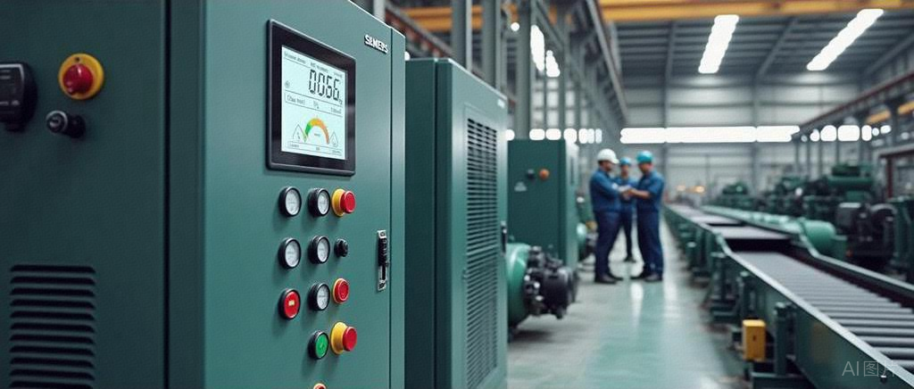
As a power source for industrial production, air compressors’ precise control directly affects production efficiency and energy consumption levels. This article details the intelligent control scheme for compressors based on Siemens PLC.
1. Hardware Configuration
1.1. PLC and Expansion Module Selection
For medium to large air compressor control systems, it is recommended to use the S7-1200 series PLC as the main control unit. For dual or multiple machine control, the CPU 1215C model can be selected, which has sufficient I/O resources and good communication capabilities.
For systems with a large number of I/O points, the SM1223 digital expansion module and SM1231 analog input module can be added. This configuration is suitable for processing signals from multiple pressure, temperature, and flow sensors, and can control multiple solenoid valves and inverters.
1.2. I/O Point Allocation Table
| Address | Type | Description | Remarks |
|---|---|---|---|
| I0.0 | DI | Start Button | Panel Input |
| I0.1 | DI | Stop Button | Panel Input |
| I0.2 | DI | Emergency Stop Button | Normally Closed Contact |
| I0.3 | DI | Pressure Switch | High Pressure Protection |
| I0.4 | DI | Temperature Switch | Overheat Protection |
| I0.5 | DI | Oil Level Switch | Low Oil Level Protection |
| I0.6 | DI | Flow Switch | Cooling Water Flow |
| I1.0 | DI | Power Monitoring | Power Status Detection |
| Q0.0 | DO | Main Motor Start | Contactor Control |
| Q0.1 | DO | Fan Control | Cooling System |
| Q0.2 | DO | Drain Valve | Timed Drain |
| Q0.3 | DO | Load Solenoid Valve | Pressure Control |
| Q0.4 | DO | Fault Indicator Light | Red |
| Q0.5 | DO | Running Indicator Light | Green |
| IW64 | AI | Pressure Sensor | 4-20mA |
| IW66 | AI | Temperature Sensor | PT100 |
| QW80 | AO | Inverter Control | 0-10V |
2. Control Program Design
2.1. Program Architecture
The air compressor control program adopts a layered design, ensuring a clear program structure for easy maintenance:
OB1: Main program loop, calls various function blocks
FB1: System Initialization
FB2: Pressure Control
FB3: Temperature Monitoring
FB4: Fault Diagnosis
FB5: Timed Drain
FB10: HMI Communication Processing
DB1: System Parameter Data Block
DB2: Operating Status Data Block
DB3: Fault Record Data Block
2.2. Core Function Block Design
Taking the pressure control function block as an example, the key code design is shown below:
pascal
FUNCTION_BLOCK "Pressure Control" // FB2
{ S7_Optimized_Access := 'TRUE' }
VERSION:0.1
VAR_INPUT
ActualPressure:Real; // Current system pressure
TargetPressure:Real; // Set pressure value
PressureDifference:Real; // Hysteresis
OperatingMode:Int; // 1=Automatic, 2=Manual
END_VAR
VAR_OUTPUT
LoadCommand:Bool; // Load control
UnloadCommand:Bool; // Unload control
InverterOutput:Real; // Inverter output
END_VAR
VAR
PressureTooHigh:Bool;
PressureTooLow:Bool;
StableZone:Bool;
UpperLimit:Real;
LowerLimit:Real;
END_VAR
BEGIN
// Calculate pressure control range
UpperLimit := TargetPressure + PressureDifference / 2;
LowerLimit := TargetPressure - PressureDifference / 2;

// Determine pressure status
PressureTooHigh := ActualPressure > UpperLimit;
PressureTooLow := ActualPressure < LowerLimit;
StableZone := NOT PressureTooHigh AND NOT PressureTooLow;

// Automatic control mode
IF OperatingMode = 1 THEN
// Load control logic
IF PressureTooLow THEN
LoadCommand := TRUE;
UnloadCommand := FALSE;
// Inverter speed increase logic
InverterOutput := 50.0 + (LowerLimit - ActualPressure) * 10.0;
// Limit output range
IF InverterOutput > 100.0 THEN
InverterOutput := 100.0;
END_IF;
END_IF;

// Unload control logic
IF PressureTooHigh THEN
LoadCommand := FALSE;
UnloadCommand := TRUE;
// Inverter speed decrease logic
InverterOutput := 50.0 - (ActualPressure - UpperLimit) * 10.0;
// Limit output range
IF InverterOutput < 30.0 THEN
InverterOutput := 30.0;
END_IF;
END_IF;

// Stable zone control
IF StableZone THEN
LoadCommand := TRUE;
UnloadCommand := FALSE;
// Maintain current speed
END_IF;
END_IF;

// Manual control mode retains current state
END_FUNCTION_BLOCK
2.3. State Control Design
The air compressor control system adopts a state machine design, including the following main states:
Standby State: System powered on but not started
Startup Preparation: System check phase
No Load Operation: Motor running but not generating pressure
Load Operation: Normal working state
Unload Operation: Unloading after reaching pressure upper limit
Cooling Operation: Overheat protection state
Fault Shutdown: Abnormal state
Normal Shutdown: Controlled shutdown process
3. Fault Diagnosis and Troubleshooting
3.1. Common Fault Analysis
| Fault Phenomenon | Possible Causes | Diagnosis Method | Handling Measures |
|---|---|---|---|
| Unable to Start | Power failure, emergency stop pressed, protection switch triggered | Check all safety circuit input signals | Reset protection device, check power supply |
| Unstable Pressure | Pressure sensor failure, improper control parameters | Monitor pressure sensor signals, check adjustment parameters | Calibrate sensor, optimize PID parameters |
| Frequent Load/Unload | Pressure difference setting too small | Check pressure difference parameter in the program | Appropriately increase pressure difference |
| High Temperature | Cooling system failure, fan not working | Check cooling water flow, fan operation status | Restore cooling system, clean radiator |
| Oil Level Alarm | Lubricating oil leakage, sensor failure | Check oil level, sensor connection | Add lubricating oil, replace sensor |
3.2. Use of Diagnostic Tools
Siemens TIA Portal provides various diagnostic tools for quick fault location in compressors:
Online Monitoring: Real-time observation of variable value changes
Forced Table: Forcing key signals to verify control logic
Alarm Display: Integrated alarm function of the system
Trend Recording: Records trends of key parameter changes
4. HMI Design
4.1. Interface Layout
The design principle of the HMI interface for air compressors is simplicity and intuitiveness, including the following main pages:
Main Page: Displays system operating status, key parameters, and alarm information
Parameter Settings: Adjust control parameters such as pressure set value, difference, etc.
Manual Control: Perform manual load/unload operations
Alarm Page: View current and historical alarms
Trend Chart: Displays trends of parameters such as pressure and temperature
4.2. Parameter Settings
Key parameter settings include:
Target Pressure Value: 0.6-0.8MPa
Pressure Difference: 0.05-0.15MPa
Unload Time: 30-180 seconds
Automatic Drain Interval: 30-240 minutes
Drain Duration: 2-10 seconds
Overheat Protection Temperature: 85-95°C
5. System Maintenance and Management
5.1. Daily Maintenance Points
To ensure the long-term reliable operation of the compressor control system, the following maintenance work is required:
Regular Backup: Backup PLC programs and parameters quarterly
Sensor Calibration: Calibrate pressure sensors every six months
I/O Point Check: Monthly check of all input and output signals
Log Analysis: Regularly analyze operation logs to identify abnormal trends
Electrical Check: Quarterly check of all electrical connections and grounding
5.2. System Upgrade Method
System upgrades should follow these steps:
1. Backup current programs and parameters
2. Develop a detailed upgrade plan and rollback scheme
3. Execute upgrades during non-production hours
4. Test new functions step by step
5. Document all changes and update documentation
6. Conclusion
The air compressor control system based on Siemens PLC can achieve efficient and stable operation through reasonable hardware configuration, hierarchical program design, and a well-designed human-machine interface. If you have any compressor control issues, feel free to discuss!