Seven Steps to Easily Debug PLCs: A Quick Start for Electrical Beginners!
Electrical beginners often encounter a challenge after completing the design of electrical control cabinets and PLC programs: how to start debugging? If the method is improper, it may lead to serious issues such as burning out the PLC. Today, I will introduce a simple and practical seven-step debugging process to help you successfully debug the system.
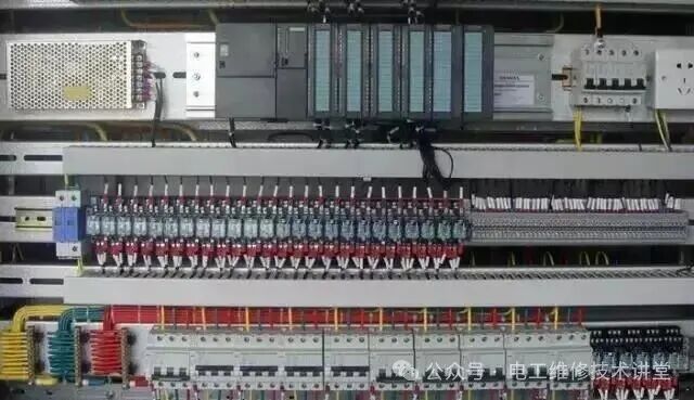
Step 1: Check the Circuit Diagram (Power Off)
First, ensure that the circuit diagram is complete and accurate. The PLC system’s diagrams usually include internal wiring diagrams and external wiring diagrams. Two points need to be confirmed:
1. Whether the design of the diagram is reasonable and whether the component capacities match.
2. Strictly connect the components according to the diagram.
The focus is on checking the power supply part:
Ensure there are no short circuits.
Strong current (220V) and weak current (24V) must be strictly separated. Especially for the PLC’s 24V power supply, if connected incorrectly to 220V, it can easily burn out the PLC or expansion modules.
Step 2: Check the PLC External Circuit (Point Testing)
After confirming the power supply is correct, power on and start the “point testing”. This step involves testing each input and output point individually, including:
Buttons, emergency stop buttons, indicator lights, cylinders, limit switches, etc.
The testing method is to operate the buttons on-site while another person monitors the input and output signals on the PLC.
For large systems, it is recommended to create a test sheet to record the test results. If wiring errors are found, correct them promptly.
Note: Before testing, be sure to back up the PLC program and clear or disable the program to avoid erroneous actions during testing.
Step 3: Check the Mechanical Structure and Test Motor Loads
This stage mainly checks whether the mechanical structure is secure and whether the motor loads are properly protected to avoid accidents caused by unexpected events. Then conduct a manual test run:
Check if the motor can rotate forward and backward.
For frequency converters, set the appropriate parameters and optimize the motor.
For vertical loads (such as lifting equipment), be sure to have professionals operate to avoid control errors.
Step 4: Manual Mode / Semi-Automatic Mode Debugging
Manual mode debugging is to ensure that the equipment can operate according to the predetermined logic. During the testing process, pay special attention to safety functions:
Test whether the emergency stop, light curtain, and other safety devices are effective.
Manual mode can also operate the equipment through buttons or HMI, simulating the workflow under automatic mode to ensure the equipment operates normally in this state.
Step 5: Debug Automatic Mode According to Production Process
After completing the manual mode debugging, the next step is to debug the automatic mode. At this time, special attention should be paid to various interlocking functions:
Logical interlocks
Safety interlocks
Various operations in the production process
Be sure to conduct multiple cycle tests to ensure the system can run continuously and stably, avoiding any deadlocks or errors.
Step 6: Debug Special Process Functions
The PLC system, in addition to basic logic control, may also involve some special functions, such as PID control. Debugging at this stage is usually more complicated and requires patience to adjust:
Select appropriate control parameters.
For PID control, some PLCs provide auto-tuning functions, but this process still takes a long time to complete.
Step 7: Pre-Production Testing and Acceptance
After completing all debugging steps, enter the pre-production stage. This is the final inspection before formal production:
Test whether the production rhythm is appropriate.
Check whether the safety functions remain effective under load testing.
After a period of continuous testing, if the system can run stably, it can be handed over.
Beginner’s Tip:
During the debugging process, be especially careful with the power supply part. For example, when I first started debugging, I once burned out a digital input module because the construction unit connected the 220V contact of the belt pull switch to the 24V contact. This lesson taught me to always distinguish between 220V and 24V power supplies to avoid similar issues.
The above seven steps, step by step, help you master PLC debugging skills from basic to advanced, allowing you to easily tackle electrical debugging challenges!