1. Sensors
1.1 KY -xxxx Series
KY-002
-
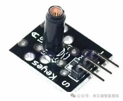
KY-002 is a vibration sensor, consisting of a conductive shell and an internal spring assembly.
During vibration, the shell contacts the internal spring and sends a signal.
-
The KY-002 vibration switch module has three pins: VCC, GND, and SIG. VCC is the positive power supply, GND is the negative power supply, and SIG is the output signal.
The output signal of the KY-002 vibration switch module is a brief high-level signal. When the module is moved, the spring mechanism closes the circuit and sends a brief high-level signal.
KY-003
-
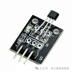
KY-003 is a Hall effect sensor that changes its output based on the presence of a magnetic field. This means that the output signal generated by the Hall effect sensor is a function of the magnetic field density around it. According to the information I found, the output signal of the KY-003 module is a voltage signal. When the magnetic flux density around it exceeds a preset threshold, the sensor detects it and generates an output voltage, sometimes referred to as Hall voltage, to indicate the presence of a magnetic field.
-
KY-003 has three pins: VCC, GND, and OUT. VCC is the power pin, GND is the ground pin, and OUT is the signal output pin.
KY-004
-
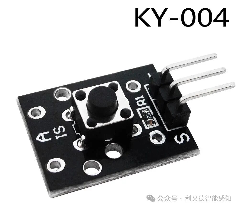
KY-004 is a button switch module that closes the circuit and sends a high-level signal when pressed. It has three pins: S (signal), + (positive), and – (negative).
-
When the button is pressed, the S pin outputs a high-level signal.
KY-005
-
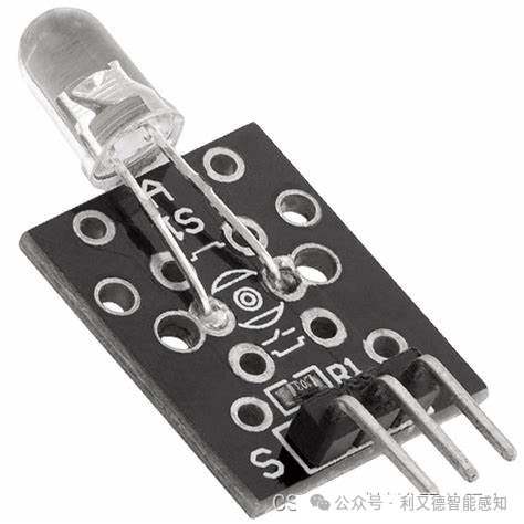
KY-005 is an infrared transmission module that can send encoded infrared signals at a frequency of 38kHz and a wavelength of 940nm. This module is generally used in conjunction with the KY-022 infrared receiver.
-
Here is the pin description for the KY-005 module:
Signal: Digital signal output
Ground: Ground
VCC: Positive power supply (+5V)
KY-006
-
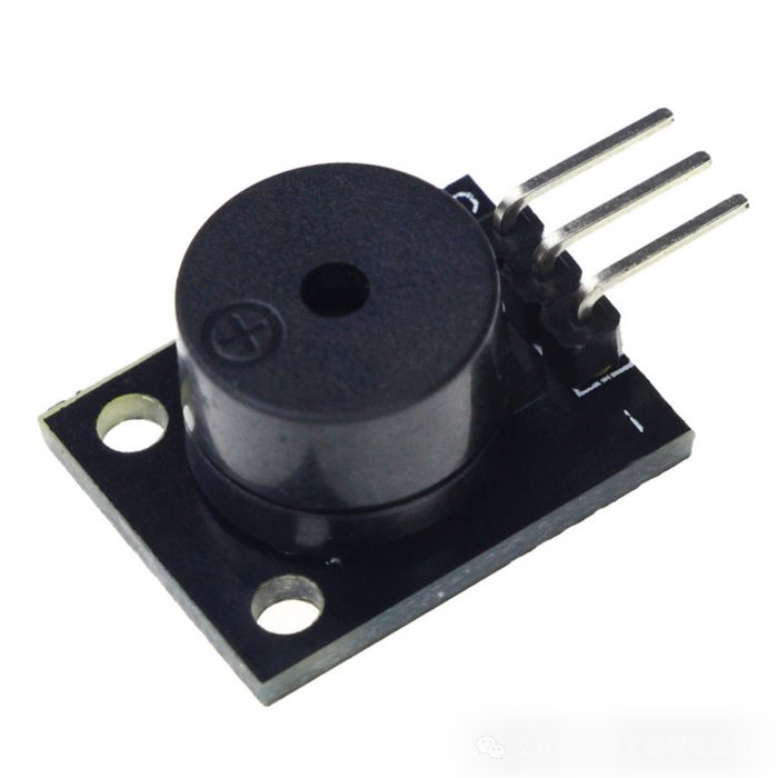
KY-006 is a passive piezoelectric buzzer module that can produce audible sounds of different frequencies using pulse width modulation (PWM). It can generate a range of tones and sounds based on the input. Therefore, it is commonly used to create short sound effects or simple musical notes.
-
KY-006 module has three pins: VCC, GND, and SIGNAL.
-
The VCC pin connects to the positive terminal, the GND pin connects to the negative terminal,
-
and the SIGNAL pin connects to the digital output pin of the controller. When the controller outputs a high signal, the KY-006 module will produce sound.
KY-007
KY-008
-
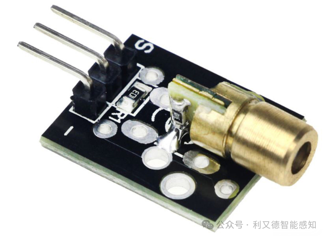
KY-008 is an infrared alarm sensor that includes a 650nm red laser diode head and a resistor. Its operating voltage is 5V, with an output power of 5mW and a wavelength of 650nm. The connection for each pin of the KY-008 laser head is as follows:
-
GND: Ground
-
+: Positive S: Signal output
-
The S output is a digital signal. When the laser emitter emits laser light, the S output is high (5V),
-
otherwise it is low (0V).
KY-009
-
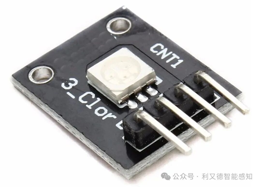
KY-009 is an RGB full-color LED module that emits various colors of light by mixing red, green, and blue light. Each color can be adjusted using PWM.
-
KY-009 module has 4 pins: GND, VCC, SCL, and SDA.
-
Among them, GND and VCC are the power interfaces of the module, while SCL and SDA are the data transmission interfaces of the I2C bus.
-
Here, the GND pin connects to the negative power supply, the VCC pin connects to the positive power supply, and the SCL and SDA pins connect to the SCL and SDA interfaces of the I2C bus.
KY-010
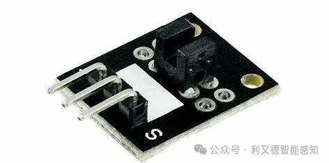
KY-010 module is a light-blocking sensor. When an object blocks the light, the module outputs a high-level signal. This module has three pins: VCC, GND, and OUT. Among them, VCC and GND connect to the positive and negative terminals of the power supply, and the OUT pin connects to the input of the microcontroller.
KY-011
KY-012
-
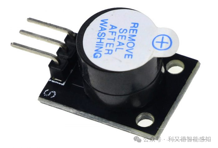
KY-012 is an active piezoelectric buzzer module, consisting of an active piezoelectric buzzer and three female header pins. When the signal is high, it produces a sound of approximately 2.5kHz.
-
This module does not require pulse width modulation (PWM) or any additional complex code; it only needs to set the signal pin to high.
-
KY-012 has a minimum/maximum operating voltage of +3.3V to +5V, with a maximum current of 30mA.
-
KY-012 has three pins: positive (+), negative (-), and signal (S) pin. When the signal pin is high, it produces a sound of approximately 2.5kHz.
KY-013
-
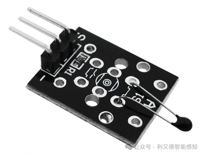
KY-013 is an analog temperature sensor module that can measure the ambient temperature based on the resistance value of the onboard thermistor. The module consists of an NTC thermistor, a 10kΩ resistor, and three male header pins. The resistance of the NTC thermistor changes with temperature; as the temperature increases, its resistance decreases, and conversely, as the temperature decreases, its resistance increases. Therefore, the ambient temperature can be calculated by measuring the resistance of the NTC thermistor. The KY-013 module is compatible with popular electronic platforms such as Arduino and ESP32.
S: Signal output
+: Positive
-: Negative
KY-014
KY-017
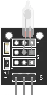
KY-017 is a mercury tilt switch module that can detect motion or tilt status. It consists of a 10KΩ resistor and a bidirectional conductive metal ball switch. When the module tilts to a certain angle, the switch opens or closes the circuit. It cannot measure the angle of tilt. Its operating voltage is 3.3V to 5V, and the output type is a digital signal. You can use it for simple motion control or safety alarm projects.
KY-018
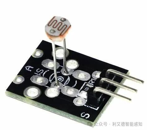
KY-018 sensor has three pins: VCC, GND, and SIGNAL. Among them, VCC is the positive power supply, GND is the negative power supply, and SIGNAL is the signal output. When the light intensity changes, the KY-018 sensor outputs an analog signal that is proportional to the light intensity.
KY-019
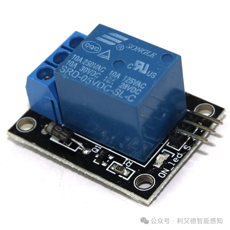
KY-019 is a 5V relay module that can be used to control AC or DC circuits. It has an LED that indicates the signal level. It also has three contact points: Normally Closed (NC), Common (COM), and Normally Open (NO). You can safely control high-voltage devices using low-voltage devices like Arduino or Raspberry Pi.
KY-020
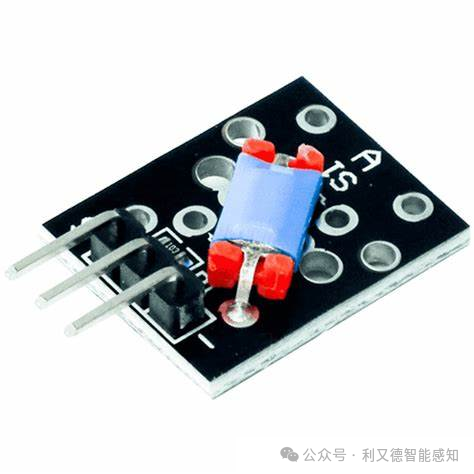
KY-020 is an inclination switch sensor module that consists of a 10kΩ resistor and a bidirectional conductive metal ball switch. This switch opens/closes the circuit based on the degree of tilt. It has three pins: VCC, GND, and SIG. VCC is the positive power supply, GND is the negative power supply, and SIG is the signal output port.
-
The SIG pin of the KY-020 module is the output pin, which can output high or low levels. When the tilt switch module is tilted, the SIG pin outputs a low level; otherwise, it outputs a high level.
KY-021
-
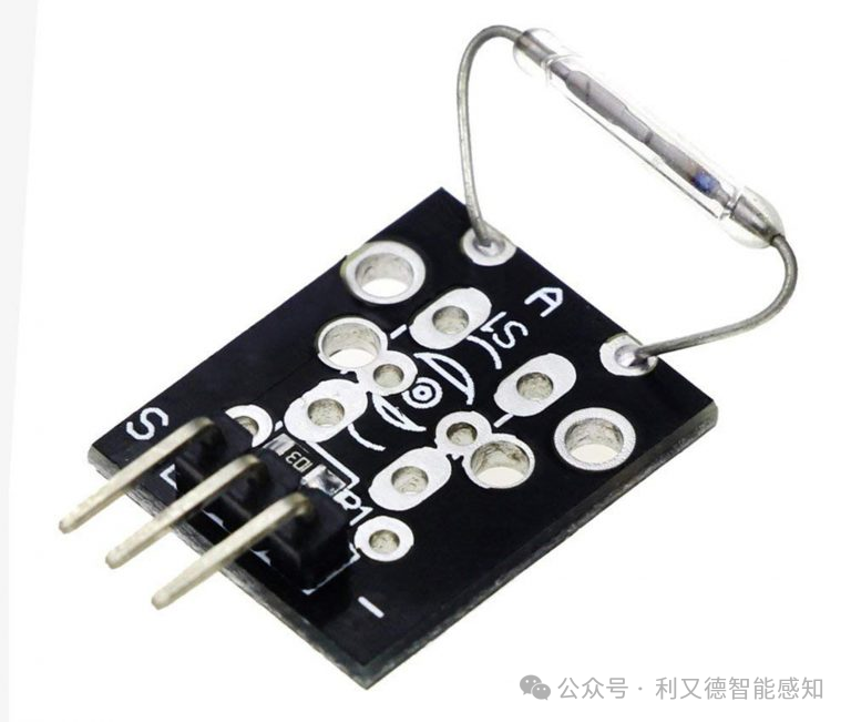
KY-021 is a magnetic switch module that sends a digital signal when exposed to a magnetic field. It is commonly used in mechanical systems as a proximity sensor. It has three pins: GND, VCC, and SIGNAL.
-
The SIGNAL pin of the KY-021 is a digital output pin. When the magnetic switch module is exposed to a magnetic field, it sends a digital signal. The level of the digital signal is either high (5V) or low (0V).
KY-024
-
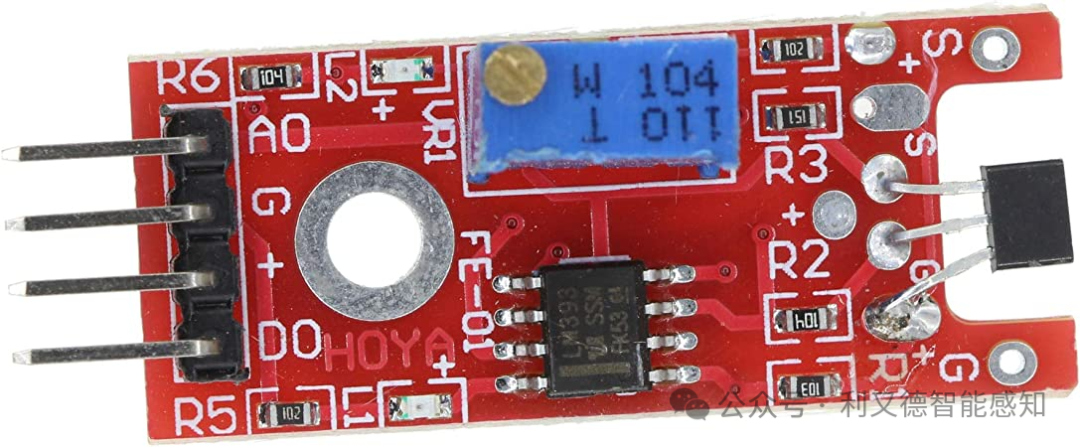
KY-024 linear magnetic Hall sensor is a highly sensitive magnetic field detection sensor with the following features:
-
Main chip: LM393, 3144 Hall sensor magnetic induction probe.
-
Operating voltage: DC 5 volts.
-
Has signal output indication.
-
Includes mounting holes for easy installation.
-
Outputs effective signal as low level.
-
Sensitivity adjustable (fine-tuning).
-
KY-024 linear magnetic Hall sensor has four pins: VCC, GND, DO, and AO.
-
Among them, VCC and GND are the power pins, DO is the digital output pin, and AO is the analog output pin. When a magnetic field is detected, the DO pin outputs a low-level signal, and the AO pin outputs an analog signal.
KY-025
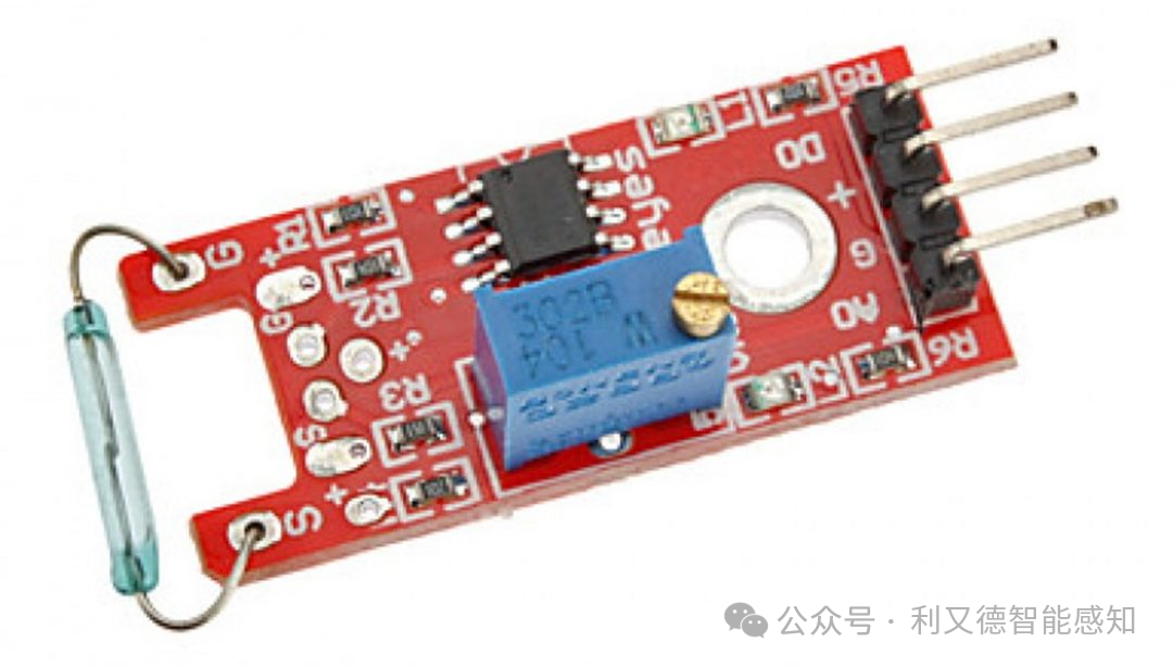
KY-025 is a reed switch module, which is a small electrical switch typically operated by a magnetic field applied nearby. This module has both digital and analog outputs, with the following pin descriptions:
S: Digital output
G: Ground
+: Power
KY-027
-
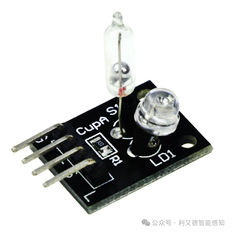
KY-027 module consists of a mercury switch, LED, and a 10kΩ resistor. Each board has a pin to control the switch, LED, power, and ground.
-
“S” stands for “Signal”, which is the signal pin; “L” stands for “Light”, which is the pin for the light-sensitive resistor.
-
The “S” and “L” pins of the KY-027 module are the signal pin and the light-sensitive resistor pin, respectively. The working principle of the light-sensitive resistor is that when light shines on it, its resistance changes, thereby altering the output voltage of the KY-027 module. The signal pin is used to control the mercury switch and the brightness of the LED.
KY-028
-
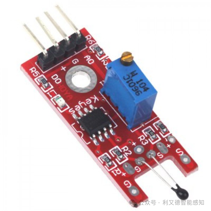
KY-028 module is a temperature sensor module with 4 pins.
-
VCC: Positive power supply
-
GND: Negative power supply
-
D0: Digital output
-
A0: Analog output
-
The A0 pin outputs an analog signal, and its voltage value is proportional to the detected physical quantity.
-
The D0 pin outputs a digital signal. When a physical quantity is detected, it will output either a high or low level.
KY-029
-
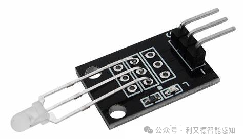
KY-029 adopts a common cathode design, where the negative terminal of the LED is connected to the negative terminal of the sensor. When the LED emits green light, the red LED is off; when the LED emits red light, the green LED is off. This achieves the design of a two-color LED common cathode sensor module.
-
It has a 3-pin interface: VCC, GND, and OUT. Among them, VCC is the positive terminal, GND is the negative terminal, and OUT is the output signal. When KY-029 detects light, it outputs a high-level signal; otherwise, it outputs a low-level signal.
KY-031
-
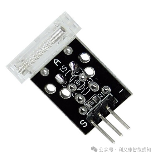
KY-031 knock sensor is a spring-based sensor that generates a high-level signal when vibration is detected. It can be widely used in security systems or monitoring. According to search results,
-
KY-031 pin description is as follows:
-
VCC: Positive power supply
-
GND: Negative power supply
-
SENSE: Signal output port
-
The signal output port SENSE of the KY-031 knock sensor will generate a high-level signal when vibration is detected.
KY-032 Infrared Sensor
-
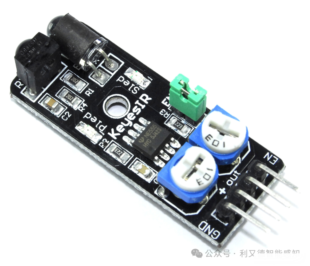
KY-032 is an adjustable distance infrared proximity sensor, also known as AD-032. Its detection range is from 2cm to 40cm and can be adjusted by rotating the potentiometer knob.
-
This sensor has 4 pins: GND, +, S (output), and EN. Among them, S is the output pin, and EN is the enable pin. When light hits, the obstacle reflects back to the receiving LED. The module has a pair of infrared LEDs, one transmitter and one receiver. The emitted LED sends infrared light pulses at a certain frequency. This jumper keeps the module permanently enabled, so it always detects obstacles.
KY-033
-
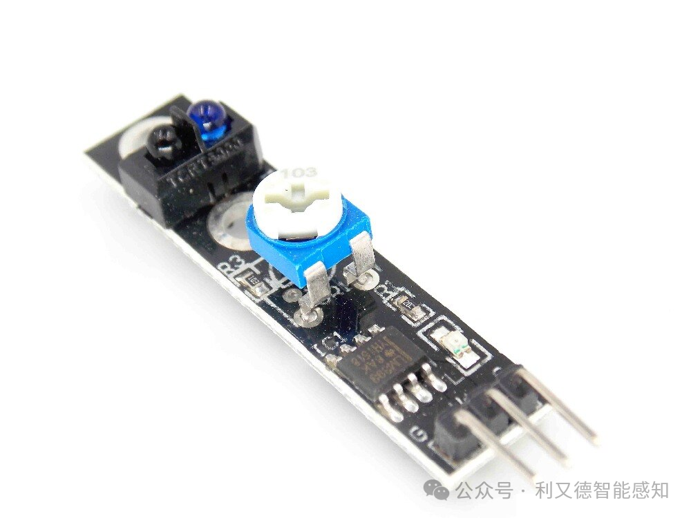
KY-033 is a tracking sensor that can be used to detect light-reflecting or light-absorbing surfaces. The module’s pins are as follows:
-
VCC: Positive power supply
-
GND: Negative power supply
-
DO: Digital output signal
-
AO: Analog output signal
-
Among them, the DO pin is the digital output signal. When a light-reflecting or light-absorbing surface is detected, it outputs a high level; when not detected, it outputs a low level.
-
The AO pin is the analog output signal, which can output different voltage values based on the detected light intensity.
KY-034
-
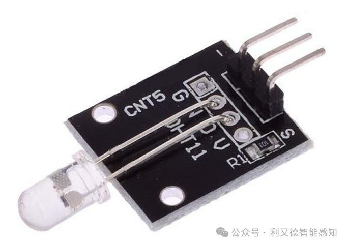
KY-034 is an automatic flashing color LED module that has a flashing LED mounted on a circuit board with a resistor.
-
VCC: Positive power supply
-
GND: Negative power supply
-
OUT: Output signal
KY-035
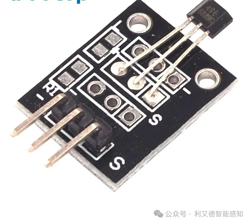
KY-035 module is a Hall magnetic sensor module, built with an AH49E linear Hall effect device, operated with the help of a magnetic source. This module changes the output voltage, which is typically set by the input supply voltage and varies proportionally with the strength of the magnetic field around the sensor. The KY-035 module has three pins: VCC, GND, and OUT. Among them, VCC and GND connect to the power supply and ground, and OUT connects to the digital input pin of the microcontroller.
KY-036
-
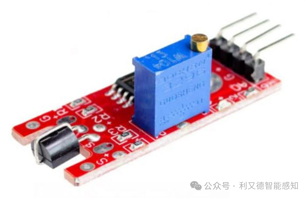
KY-036 is a touch sensor module, also known as a metal touch module.
-
It uses a KRS13 Darlington NPN transistor, with its signal controlled by the circuit part, which integrates an LM393 with two comparators. When the touch bends the bare wire on the transistor (represented by the base of the transistor), the 50 Hz signal from the environment is injected into the high-gain amplifier. The output of the amplifier is connected to the comparator, which converts the sine AC signal into a square wave.
-
KY-036 module has two digital pins and two analog pins. Among them, the D0 pin is the digital output, which outputs a high level when metal contact is detected; the A0 pin is the analog output, which can output different voltage values based on the strength of the contact. The other two pins are VCC and GND, used to connect to power and ground.
KY-038
-
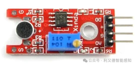
KY-038 is a high-sensitivity sound sensor module used to detect the sound intensity in the environment.
-
KY-038 module has 4 pins: VCC, GND, DO, and AO. Among them, VCC and GND are the positive and negative terminals of the module, DO is the digital output, and AO is the analog output.
-
The DO pin of the KY-038 module is the digital output. When the environmental sound intensity reaches the set threshold, the module’s DO pin outputs a low level; when the environmental sound intensity is below the set threshold, the module’s DO pin outputs a high level. The AO pin is the analog output, which can output an analog signal representing the magnitude of the sound intensity detected by the module.
KY-039
-
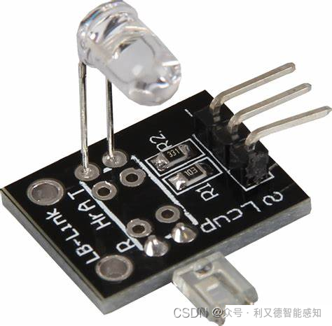
KY-039 is a heart rate sensor that can reliably detect heartbeat or pulse rate. Here is the pin description for KY-039:
-
VCC: Positive power supply
-
GND: Negative power supply
-
S: Signal output
KY-040 FOR Module
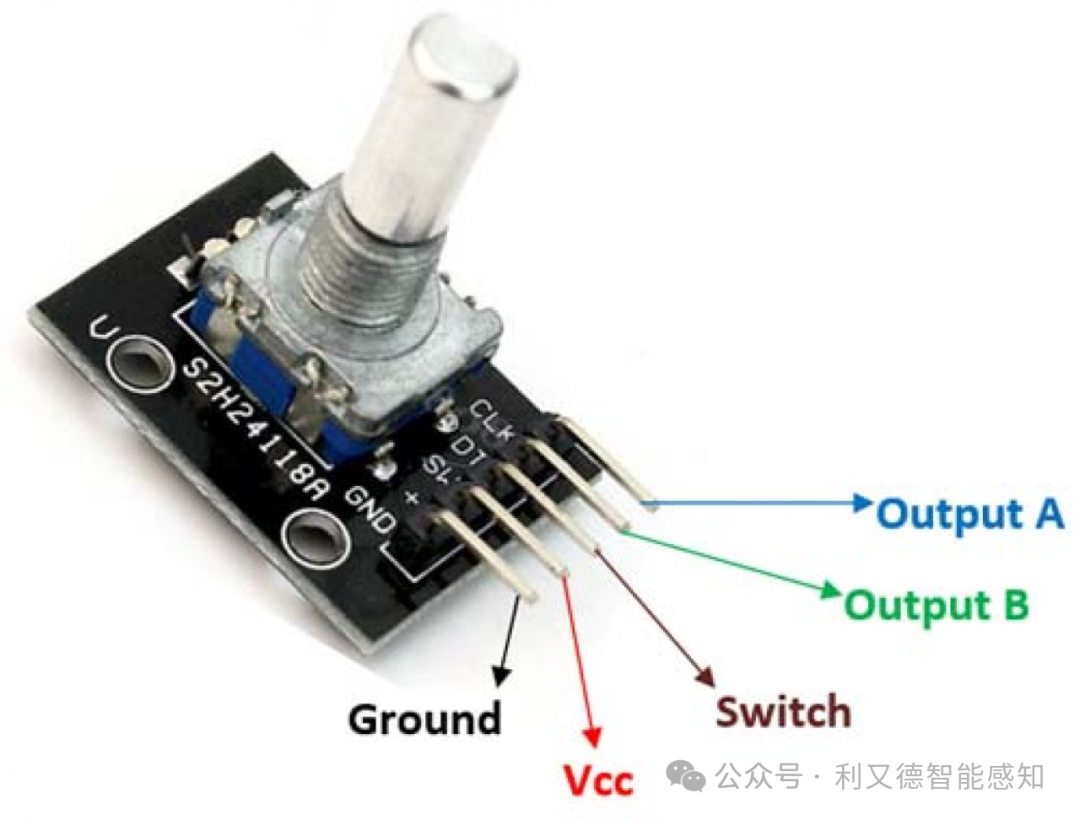
-
KY-040 rotary encoder module has 5 pins: VCC, GND, CLK, DTSW. Among them, VCC and GND are the positive and negative terminals of the power supply, CLK and DT are the output ports of the rotary encoder, and SW is the button port of the rotary encoder.
-
VCC and GND are the positive and negative terminals of the power supply, CLK and DT are the output ports of the rotary encoder, and S is the button port of the rotary encoder. The specific meaning of the CLK and DT pins is that each time the user rotates the knob, a low-level signal is generated on the DT and CLK pins. Clockwise rotation will first make the CLK pin low, then the DT pin will also become low. Counterclockwise rotation will first make the DT pin low, then the CLK pin will also become low.
1.1 HW-131
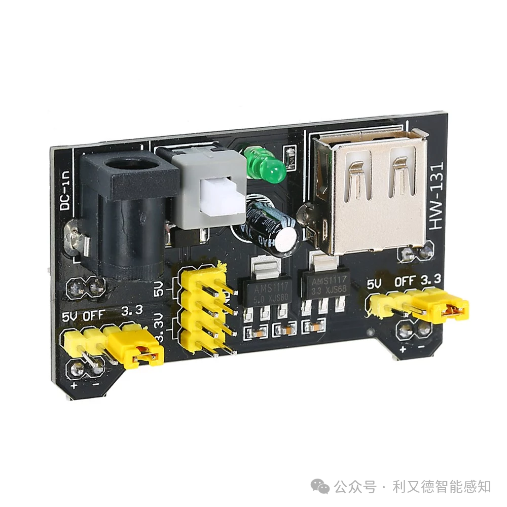
HW-131 is used to provide power to the breadboard, capable of outputting 3.3V or 5V voltage. It can input power through DC 6.5~12V or USB interface. It has two independent switches to toggle the output voltage and turn off the output. It also has two DC output pins for external use.
1.3 NRF24L01 Serial to USB Wireless Module + Wireless Transmitter and Receiver 2.4G Data Transmission Communication Module
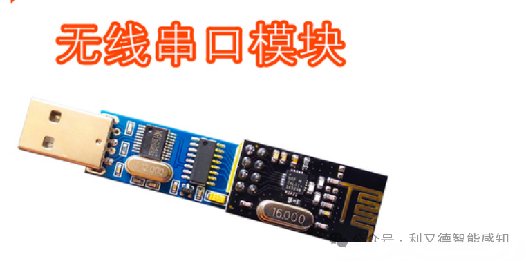
NRF24L01 Serial to USB wireless module + wireless transmitter and receiver 2.4G data transmission communication module is a wireless communication module that can achieve wireless transmission of serial data. Among them, NRF24L01 is a 2.4G wireless communication chip characterized by low power consumption, high speed, and high stability. It can achieve point-to-point, point-to-multipoint, and broadcast communication.
1.4 VS1838B Infrared Remote Control Receiver Module
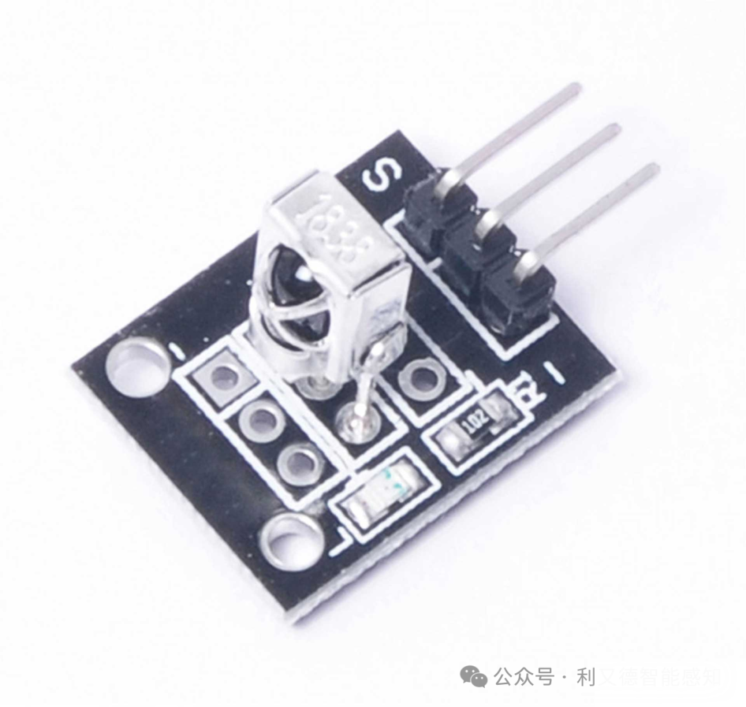
VS1838B infrared remote control receiver module is an infrared receiving module with three pins: VCC, GND, and OUT. Among them, VCC is the positive power supply, GND is the negative power supply, and OUT is the output signal. The output signal is a digital signal at TTL, CMOS levels.
When infrared light hits the VS1838B infrared remote control receiver module, it generates a current, which is amplified and processed, ultimately outputting a digital signal.
1.5 MH-SD Card Module
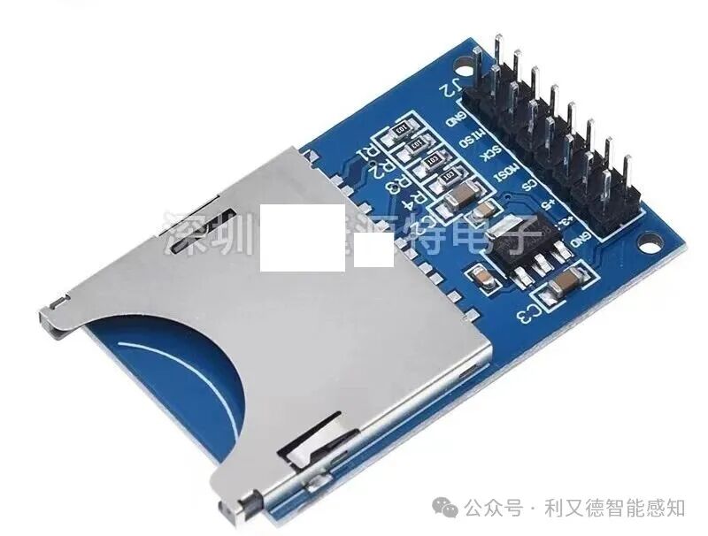
Pinout:
VCC, GND, MISO, MOSI, SCK, CS, and CD.
VCC is the power pin,
GND is the ground pin,
MISO is the pin for reading data from the SD card,
MOSI is the pin for writing data to the SD card,
SCK is the clock pin,
CS is the chip select pin,
CD is the card detection pin.
1.6 DS1302 Clock Module
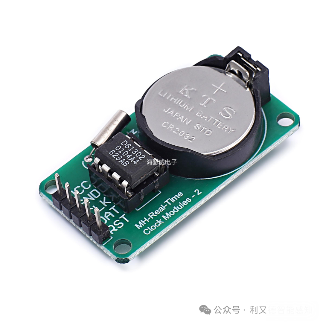
DS1302 clock module is a high-performance, low-power real-time clock circuit with RAM, capable of timing year, month, day, week, hour, minute, and second, with leap year compensation. The operating voltage is 2.5V to 5.5V. The DS1302 communicates with the microcontroller via a serial bus, requiring at least two bytes for a read/write operation. The first byte is the control byte, which is a command that tells the DS1302 whether it is a read or write operation, and whether it is for RAM or the CLOCK register.
Interface:
RST: Reset port, active low.
DAT: Serial data input/output port.
SCLK: Serial clock input port.
VCC: Power.
GND: Ground.
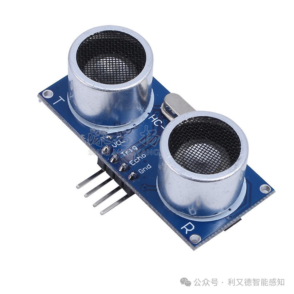
1.7 HC-SR04 Ultrasonic Sensor
-
Ultrasonic sensors typically have 4 pins: VCC (positive), Trig (trigger), Echo (response), and GND (ground).
-
Among them, VCC is the power supply, GND is the ground, Trig is the control pin used to control the emitted sound wave signal, and Echo is the receiving pin used to receive the reflected ultrasonic signal.
-
When a high signal of more than 10 microseconds is input to the Trig pin, it emits ultrasonic waves. The response pin (Echo) is the receiving end, used to receive the reflected ultrasonic signal. When the ultrasonic sensor emits ultrasonic waves, the “response” pin presents a high level before receiving the reflected ultrasonic waves.
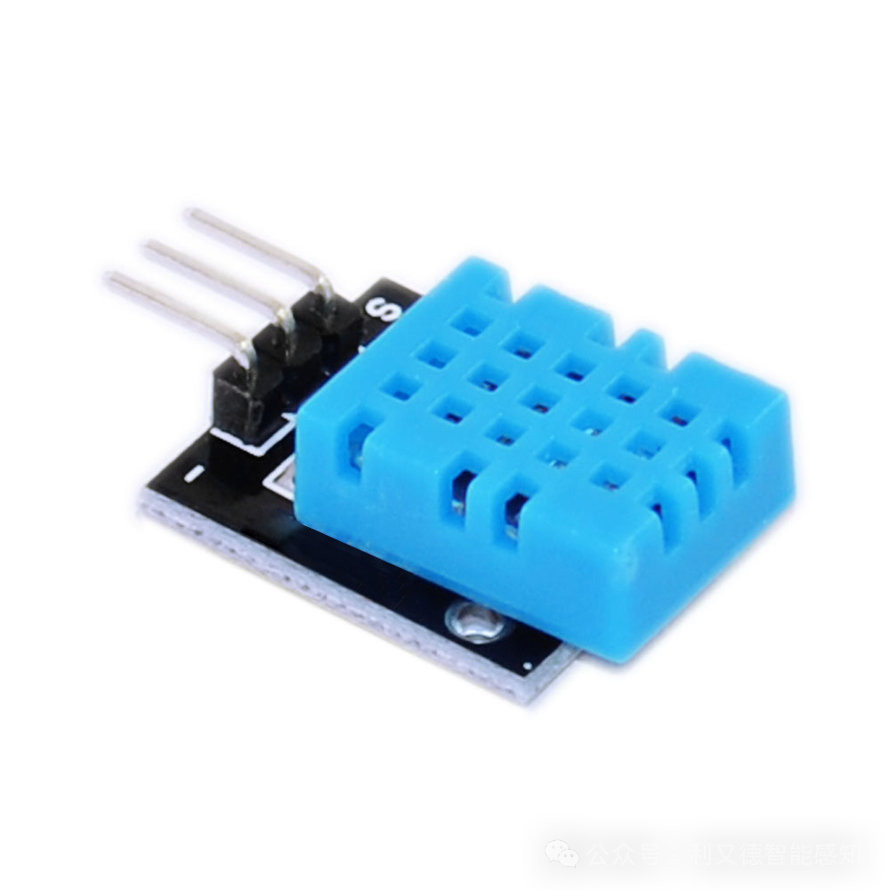
1.8 DHT11 Temperature and Humidity Sensor
-
DHT11 temperature and humidity sensor has three pins: VCC, DATA, and GND. Among them, VCC is the positive power supply, DATA is the data output pin, and GND is the negative power supply.
-
The data output signal of the DHT11 temperature and humidity sensor is a digital signal, and its output pin is a digital signal output pin that can be directly connected to the digital input of the microcontroller.
1.9 Microphone Sound Sensor
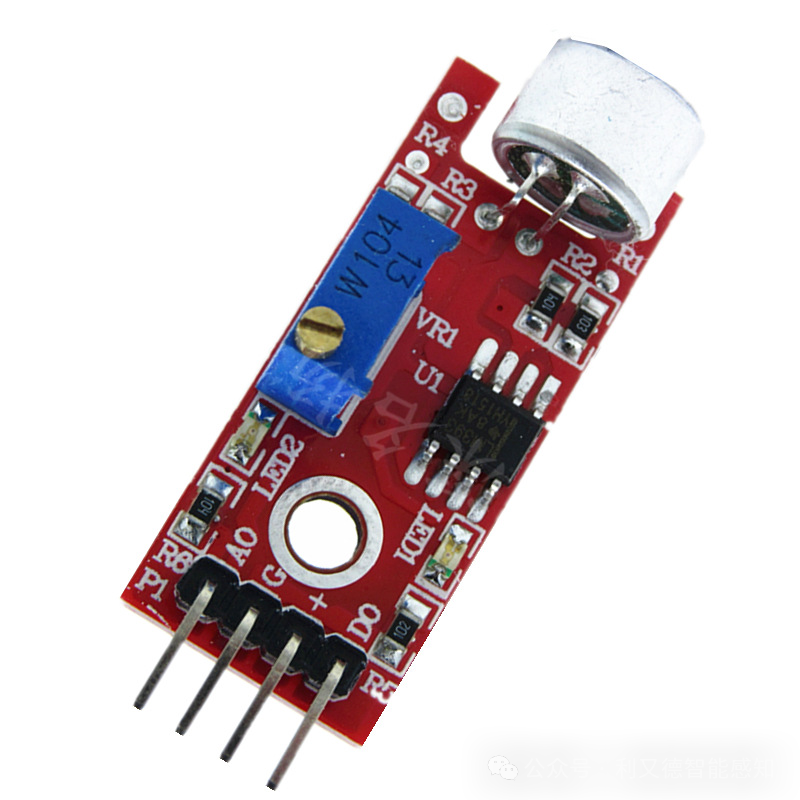
Interface:
AO represents the analog output, used to output the voltage signal detected by the microphone in real-time,
DO indicates that when the sound reaches a certain threshold, it outputs a high or low level signal;
GND represents the ground,
VCC represents the positive power supply.
1.10 JDY-31 Bluetooth Module
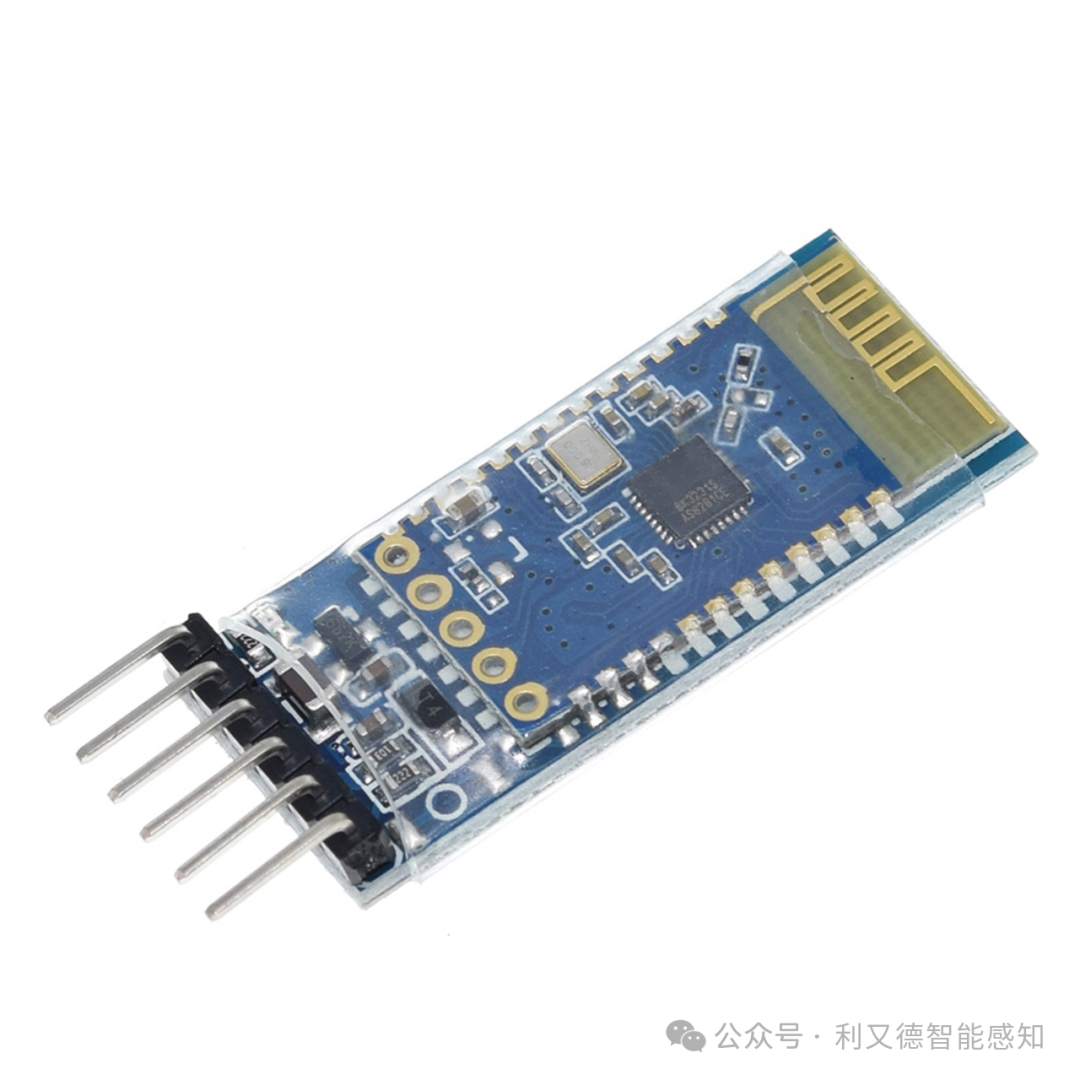
-
Pin functions of the JDY-31 Bluetooth module are as follows:
VCC: Positive power supply, 3.6V-6V
GND: Negative power supply
TXD: Serial transmission end, MCU’s TXD connects to the module’s RXD
RXD: Serial reception end, MCU’s RXD connects to the module’s TXD
-
JDY-31 Bluetooth module is a module designed based on Bluetooth 3.0 SPP, supporting data transmission for Windows, Linux, and Android, operating in the 2.4GHz frequency band, with GFSK modulation, maximum transmission power of 8dB, and maximum transmission distance of 30 meters.
-
The start and en ports of the JDY-31 Bluetooth module are empty and do not need to be connected.
1.11 MP1584EN DC-DC Buck Power Module
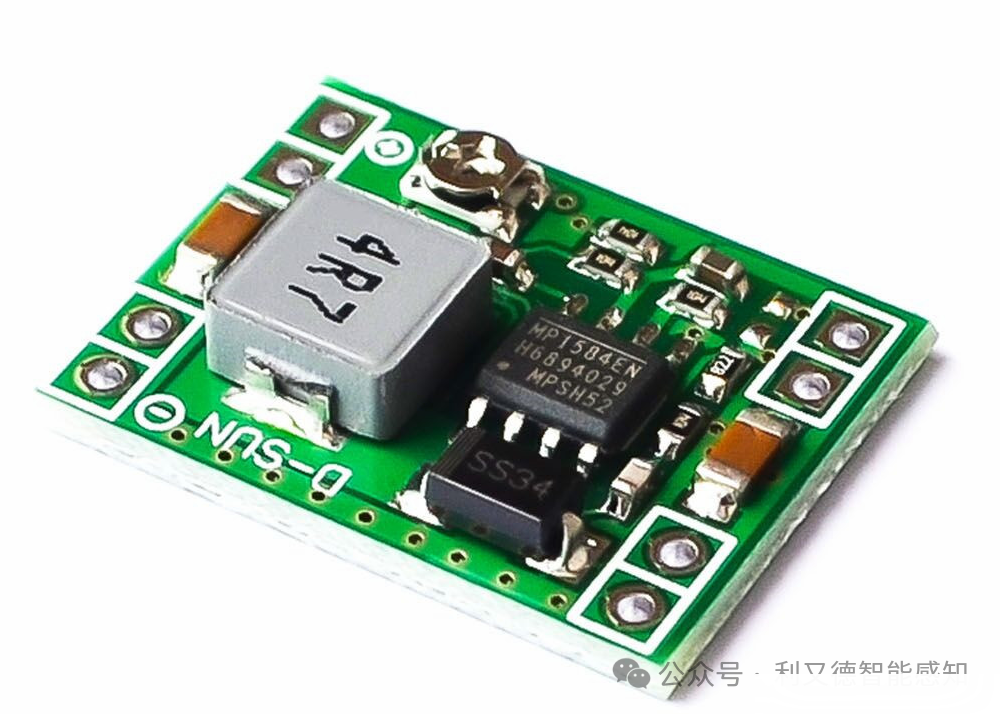
-
MP1584EN DC-DC buck power module has four pins: input positive, input negative, output positive, and output negative. Among them, the input positive and input negative are the input terminals for the DC power supply, while the output positive and output negative are the output terminals for the DC power supply.
-
The working principle of the MP1584EN DC-DC buck power module is to control the on/off of the switching tube by applying a PWM switching signal to the MOSFET Q, allowing the inductor and capacitor to charge and discharge to achieve the purpose of stepping down the power supply. The MP1584 chip has built-in short-circuit protection, with a short-circuit current threshold of 4.87A, recovering instantly after removing the overload.
-
Generally, the MP1584EN DC-DC buck power module has four pins, where VIN is the input voltage, GND is the ground, VOUT is the output voltage, and EN is the enable pin.
1.12 Soil Moisture Detection Sensor
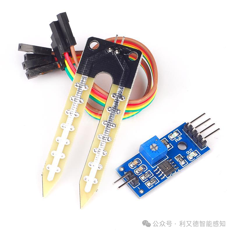
-
The soil moisture detection sensor typically consists of two components: a probe and a module. The probe has two exposed conductors that can be inserted into the soil or any other place where water content is to be measured. It acts as a variable resistor, with its resistance changing based on soil moisture.
-
The module typically has four pins: VCC pin, GND pin, A0 pin, and D0 pin.
-
The VCC pin connects to the positive power supply, the GND pin connects to the negative power supply, the A0 pin outputs the analog voltage value of the soil moisture sensor, with an output range of 0-1023, and the D0 pin outputs the switch value of the soil moisture, with values of 0 and 1.
1.13 GY-521 MPU6050
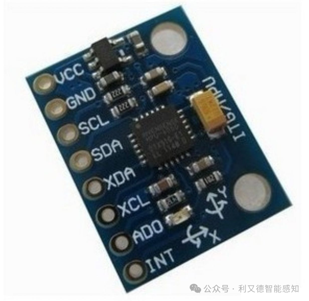
The pinout of the GY-521 MPU6050 module is as follows:
VCC: Positive power supply
GND: Negative power supply
SCL: I2C clock line
SDA: I2C data line
XDA: Auxiliary I2C data line
XCL: Auxiliary I2C clock line
AD0: Module address selection, high level is 0x69, low level is 0x68.
INT: Interrupt output, can be used to detect changes in acceleration or gyroscope data.
Among them, VCC and GND are the power pins, SCL and SDA are the I2C communication pins, AD0 is the module address selection pin, and INT is the interrupt output pin. XDA and XCL are auxiliary I2C communication pins, generally not used.
1.14 Flame Sensor
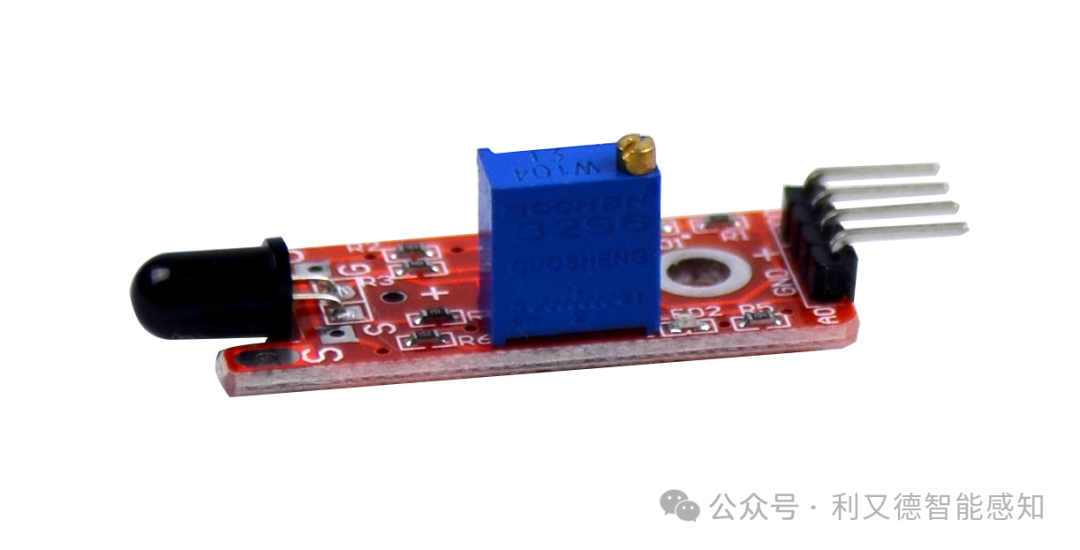
Flame sensors typically have 4 pins, two of which are power pins, and the other two are signal pins. One of the signal pins is a digital output pin (DO), and the other is an analog output pin (AO). When a flame is detected, the digital output pin outputs a low level, and the analog output pin outputs an analog value.
1.15 KY-029
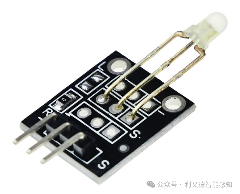
KY-029 is a bicolor LED module with three pins: VCC, GND, and S. Among them, VCC and GND are the positive and negative terminals of the power supply, and S is the signal pin. When the S pin receives a high level, the red LED lights up; when the S pin receives a low level, the green LED lights up.

Wuhan Li You De Technology Co., Ltd.
TEL:027-83621617
13296589910