Introduction
In 1979, Schneider Electric established the Modbus protocol, a bus protocol for industrial sites. Today, many industrial applications using RS485 communication adopt the Modbus protocol. So today we will learn about RS485 communication and the Modbus communication protocol.

1
Preface
In fields such as industrial control, power communication, and intelligent instrumentation, serial communication is typically used for data exchange. The initial method employed was the RS232 interface. However, due to the complexity of industrial sites and the electromagnetic interference generated by various electrical devices, signal transmission errors can occur.
In 1979, Schneider Electric established the Modbus protocol for industrial sites. Today, many industrial applications using RS485 communication adopt the Modbus protocol. So today we will learn about RS485 communication and the Modbus communication protocol.
2
RS485 Communication
1. In fact, RS232 was already in existence before RS485, but RS232 has its shortcomings:
(1) The signal voltage levels of the interface are relatively high, reaching several volts, which can easily damage the interface circuit chips. Additionally, it is not compatible with TTL levels, so a conversion circuit is necessary when connecting to microcontroller circuits.
(2) The signal lines used by the interface form a common ground communication mode with other devices. This common ground mode is susceptible to interference and has weaker anti-interference performance.
(3) The transmission distance and speed are limited, allowing communication over a maximum of only a few dozen meters; communication can only occur between two points, and multi-device networking is not possible.
2. To address the shortcomings of the RS232 interface, new interface standards such as RS485 emerged, which have the following characteristics:
(1) Logic “1” is represented by a voltage difference of + (2-6)V between the two wires; logic “0” is represented by a voltage difference of – (2-6)V between the two wires. The signal voltage levels of the interface are lower than those of RS232, making it less likely to damage circuit chips, and this level is compatible with TTL levels, facilitating connections with TTL circuits.
(2) RS485 communication is fast, with a maximum data transmission rate exceeding 10Mbps; its internal physical structure employs a balanced driver and differential receiver combination, significantly enhancing anti-interference capability.
(3) The maximum transmission distance can reach approximately 1200 meters, but the transmission speed is inversely proportional to the transmission distance. To achieve the maximum communication distance, the transmission speed must be below 100KB/s. If longer distances are required, repeaters can be used.
(4) Multiple devices can be connected to a bus for multi-device communication, allowing several transceivers to be connected on the same bus. Existing RS485 chips can connect different numbers of devices, such as 32, 64, 128, or 256.
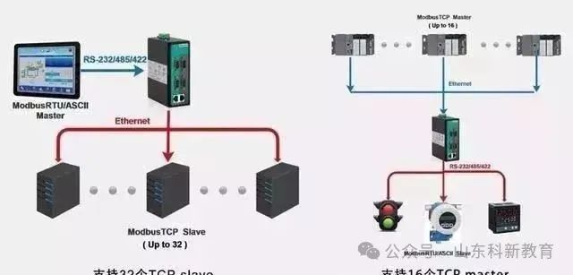
3. RS485 can be configured in two-wire or four-wire systems. The four-wire system can only achieve point-to-point communication and is rarely used today. The two-wire connection method employs a bus topology, allowing up to 32 nodes to be connected on the same bus. In RS485 communication networks, a master-slave communication mode is generally adopted, with one master controlling multiple slaves.
4. In many cases, when connecting the RS-485 communication link, a simple twisted pair is used to connect the “A” and “B” ends of each interface. However, the connection of the signal ground is often overlooked. This connection method can work normally in many situations but poses significant risks for two reasons:
(1) Common Mode Interference Issue: The RS-485 interface uses differential signal transmission, which does not require reference to a specific point for signal detection; the system only needs to detect the potential difference between the two wires. However, people often overlook that the transceiver has a certain common mode voltage range, which for RS-485 transceivers is -7 to +12V. Only when the above conditions are met can the entire network operate normally. If the common mode voltage in the network lines exceeds this range, it will affect the stability and reliability of communication, and may even damage the interface.
(2) EMI Issue: The common mode portion of the output signal from the driver needs a return path. Without a low-resistance return path (signal ground), it will return to the source end in the form of radiation, causing the entire bus to act like a huge antenna radiating electromagnetic waves.
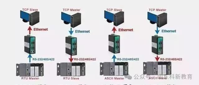
5. Since PCs typically only come with RS232 interfaces, the following methods can be used to obtain an RS485 circuit for the PC host:
(1) Use an RS232/RS485 conversion circuit to convert the PC’s RS232 serial signal to RS485. For complex industrial environments, it is best to choose surge-protected and isolated products.
(2) Use a PCI multi-serial card, selecting an expansion card that directly outputs RS485 signals.
3
Modbus Communication Protocol
The Modbus protocol is a universal language used in electronic controllers. Through this protocol, controllers can communicate with each other, and between controllers and devices over a network (such as Ethernet). It has become a universal industrial standard. With it, control devices from different manufacturers can be connected into an industrial network for centralized monitoring.

This protocol defines a message structure that a controller can recognize, describes the process by which a controller requests access to other devices, how to respond to requests from other devices, and how to detect and log errors. It establishes a common format for message domains and content.
1. Modbus has the following features:
(1) Standard and open; users can freely and confidently use the Modbus protocol without paying licensing fees or infringing on intellectual property rights. Currently, there are over 400 manufacturers supporting Modbus and more than 600 products that support it.
(2) Modbus supports various electrical interfaces, such as RS-232, RS-485, etc., and can transmit over various media, such as twisted pair, fiber optic, and wireless.
(3) The Modbus frame format is simple, compact, and easy to understand. It is user-friendly and easy for manufacturers to develop.
2. Types of Modbus Registers:
(1) Coil Status: Output ports that can set the output status of the port and also read the output status of that bit.
(2) Discrete Input Status: Input ports that change input status through external settings; they can be read but not written.
(3) Holding Registers: Certain parameters set during controller operation; they can be read and written.
(4) Input Registers: Certain parameters obtained from external devices during controller operation; they can be read but not written.
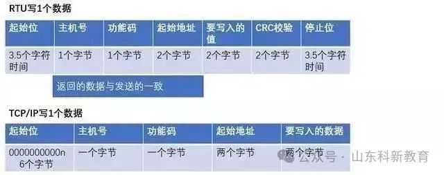
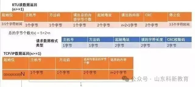
3. Modbus Communication Data Format:
(1) Single Write:
(2) Multiple Writes:
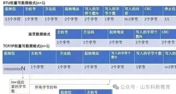
(3) Read:
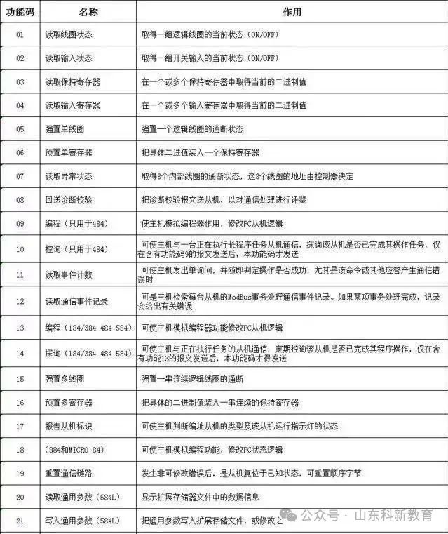
4. Brief Introduction to Modbus Function Codes:
Function codes can be divided into bit operations and byte operations, with the smallest unit for bit operations being Bit and for byte operations being 2 bytes (Byte).
(1) Bit Operation Instructions: Read Coil Status 01H, Read Discrete Input Status 02H, Write Single Coil 05H, Write Multiple Coils 0FH.
(2) Byte Operation Instructions: Read Holding Registers 03H, Read Input Registers 04H, Write Single Holding Register 06H, Write Multiple Holding Registers 10H.
5. Modbus Function Codes
Source: This article is reproduced from the internet, and the copyright belongs to the original author. If there are any copyright issues, please contact us promptly for deletion. Thank you!

Scan to Follow
WeChat ID|13615417996
Scan the left QR code for free access to
[Siemens Data Collection]