A wireless sensor network (WSN) is an emerging network technology composed of tiny wireless sensors, where nodes possess sensing, information processing, and wireless communication capabilities. WSNs have broad application prospects, widely used in military, environmental monitoring, healthcare, space exploration, and various commercial applications. Compared to other common data networks (such as the Internet, mobile ad hoc networks, telephone networks, computer networks, etc.), WSNs have some common characteristics as well as unique features. Although mature solutions from other data networks can be borrowed for WSNs, dedicated communication protocols and routing algorithms still need to be developed based on the specific uses and advantages of WSNs, which has become a pressing research topic in the field of WSNs.
The unique characteristics of WSNs, such as uncertainty, randomness, dispersive properties, multipath effects, and rapid energy decay in their communication channels, pose unprecedented challenges for WSN design. Currently, there are many critical technologies in WSN research that remain unresolved in four areas: security, energy, fault tolerance mechanisms, and network structure. The recently emerged Time Reversal (TR) algorithm has been widely applied in various technical fields such as communication, electromagnetic simulation, microwave breast cancer detection, broadband antennas, and environmental temperature monitoring. Professor Richard J. Barton from the University of Houston is also researching WSNs based on collaborative TR algorithms, but these studies are just beginning, and many technical and theoretical issues remain to be addressed.
WSNs consist of numerous nodes that require real-time detection and data processing. Generally, these nodes are powered by batteries, which have very limited energy, and replacing batteries for thousands of nodes is extremely difficult, while solar cells are evidently too bulky. To enable long-term operation of WSNs, the current solution is to formulate a working mode that keeps most nodes in adaptive sleep and wake-up states to save energy consumption, and to utilize the time reversal technology’s space-time focusing characteristics to wirelessly transmit energy to nodes that are out of power. According to the latest international research findings, combining wireless energy transmission technology with the TR algorithm is becoming an important research trend for solving energy issues in WSNs.
Current research on rectenna technology began in the early 1960s, initially applied in solar satellites, helicopter communication relay platforms, and power transmission between two ground locations to solve energy delivery issues in complex environments like deserts, islands, and canyons. Since the 1990s, advancements in microwave integration and semiconductor technology have opened new application fields for wireless energy transmission—such as micro-systems, including electronic tags and micro-mechanics. Micro-mechanics are limited in weight and battery life due to their small size, and wireless energy systems can compensate for these deficiencies.
Microwave energy transmission consists of three steps: the first step converts DC power into RF energy; the second step transmits RF energy through free space to some distant points; the third step collects the energy at the receiving point and converts it back to DC power. In wireless energy systems, the core technology is the rectenna, which efficiently converts microwaves into DC power and consists of a receiving antenna, matching network, rectifying diode, and DC load.
Research on rectennas mainly focuses on reducing the physical size of the rectenna, improving the efficiency of the diode, the efficiency of the antenna in capturing microwave energy, the rectenna conversion efficiency, and the frequency of the incident wave. With continuous improvements in diode performance and ongoing optimization of rectenna structures, the microwave-to-DC conversion efficiency can reach 90%. Additionally, the operating frequency of microwave transmission is also continuously increasing. Due to the varying atmospheric attenuation effects on microwaves at different frequencies, previous microwave transmissions tended to use a frequency of 2.45 GHz, as microwaves at this frequency experience minimal atmospheric attenuation, and related technologies are relatively mature. In recent years, with the development of high-frequency technologies, significant improvements have been made, and higher frequencies such as 5.8 GHz, 10 GHz, 35 GHz, 94 GHz, and even 245 GHz have become research directions. Moreover, using dual-frequency antennas and circularly polarized antennas as receiving antennas can enhance energy capture efficiency, which has also been implemented in mobile platforms.
Rectifying diode antennas can be classified based on the connection method between the antenna and rectifying circuit, which can be directly connected in the same plane or connected through aperture coupling; they can also be classified by the number of frequencies used into single-frequency rectenna and dual-frequency rectenna; and by the type of receiving antenna into rectennas using planar printed dipole antennas or microstrip antennas as receiving antennas. This article introduces rectifying diode antennas based on the last classification method.
2.1 Dipole Antennas as Receiving Antennas
Reference [1] introduces a printed rectenna unit, as shown in Figure 1. The entire unit is in a dual-plane form, with the printed rectifying diode antenna circuit placed parallel to a metal reflecting plate. The substrate material is Rogers Duroid 5880 with a thickness of 10 mil, where a parallel dipole antenna and a coplanar strip transmission line are printed on one side, and a low-pass filter composed of three microstrips is on the other side, which can pass 5.8 GHz signals while suppressing the higher harmonics generated by the diode, and also matches the impedance between the dipole antenna and the diode. A 47 pF chip capacitor is used to isolate RF energy from DC energy to maximize the diode’s conversion efficiency. The impedance load is placed at the terminal of the CPS (coplanar strip) band-stop filter, being 1.3 to 1.52 times the input impedance of the diode. When this rectenna operates at a frequency of 5.8 GHz with a 326 Ω load, the maximum microwave-to-DC conversion efficiency is 82%.
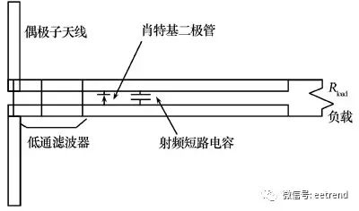
Figure 1: Structure of the 5.8 GHz Rectifying Diode Antenna Unit
Reference [2] introduces a rectifying diode antenna unit operating at 2.45 GHz, which can function as a microwave energy rectifier at 2.45 GHz and as an oscillator at 3.3 GHz. As shown in Figure 2, two aluminum strips form a dipole antenna and symmetric transmission line, with a half-wave dipole, two low-pass filters, a diode, and output capacitor constituting the rectenna. The low-pass filter prevents high-order harmonics from re-radiating through the dipole antenna, and the output capacitor shorts the RF energy, with a load impedance of 165 Ω. As a rectifier, its RF-to-DC conversion efficiency is 85%; as an oscillator, its DC-to-RF conversion efficiency is 1%.
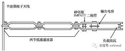
Figure 2: Structure of the Half-Wave Dipole Rectifying Antenna Unit
Dual-frequency dipole rectifying diode antennas can select one of two frequencies for energy transmission based on energy availability. Reference [3] introduces a novel dual-frequency rectifying diode antenna operating at 2.45 GHz and 5.8 GHz, as shown in Figure 3. This rectenna consists of one dual-frequency dipole antenna, one coplanar strip input filter, two CPS band-stop filters, one rectifying diode, and one microwave blocking capacitor. The dual-frequency dipole antenna has bidirectional radiation and a double-sided structure, with the long dipole antenna operating at 2.45 GHz and the short dipole antenna operating at 5.8 GHz. To increase the antenna gain and achieve unidirectional radiation, a reflecting plate is added 17 mm below the antenna. The CPS low-pass filter is composed of a band-stop filter with a cutoff frequency of 7 GHz, allowing signals at 2.45 GHz and 5.8 GHz to pass while suppressing the second-order harmonic at 11.6 GHz in the 5.8 GHz signal, but also allowing the second-order harmonic at 4.9 GHz and the third-order harmonic at 7.35 GHz in the 2.45 GHz signal to pass. To resolve this issue, a new T-shaped band-pass filter can be added to the CPS strip to suppress the high-order harmonics at 4.9 GHz and 7.35 GHz, with the lengths of the band-stop filters for suppressing the second-order harmonic at 4.9 GHz being 20.1 mm and for the third-order harmonic at 7.35 GHz being 10.5 mm, as shown in Figure 4. Under the operating frequencies of 2.45 GHz and 5.8 GHz, the conversion efficiencies of the rectenna constructed with the new dual-frequency printed dipole antenna and the new CPS filter can reach 84.4% and 82.7%, respectively.
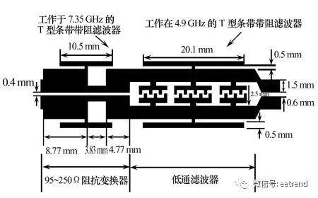
Figure 3: Structure of the Dual-Frequency Rectifying Diode Antenna
Figure 4: Structure of the CPS Low-Pass Filter with Band-Stop Filter
2.2 Microstrip Antennas as Receiving Antennas
Reference [4] introduces a micro rectifying diode antenna with an integrated band-stop filter operating at 5.5 GHz. The substrate has a double-layer structure, with the upper layer made of Duroid 5880, thickness 3.175 mm, housing the receiving antenna, and the lower layer made of RO4003, thickness 1.524 mm, containing the band-stop filter, with a common ground plane between the two substrates. Two interconnected slots are opened along the diagonal of the patch on the patch antenna to generate right-handed circularly polarized waves. The rectifying antenna measures 40 mm × 40 mm × 4.7 mm, while the microstrip antenna measures 14.8 mm × 14.8 mm. The filter structure is shown in Figure 5, where at 5.5 GHz, the filter has less than 1 dB insertion loss; at 11 GHz, the insertion loss of the filter reaches 50 dB, effectively suppressing the second-order harmonic at 11 GHz. Measurements show that when the transmitting and receiving antennas are 40 cm apart and the transmission power is 7 W, the maximum output voltage is 2.15 V, with a maximum conversion efficiency of 74%; and when the energy density exceeds 0.75 mW/cm², the conversion efficiency approaches a constant. This rectifying diode antenna can be used to receive microwave energy at 5.5 GHz and also for data communication at 5.15–5.35 GHz.
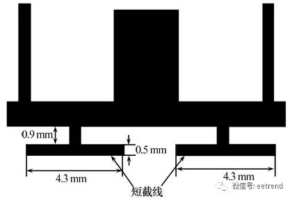
Figure 5: Structure of the Micro Rectifying Diode Antenna with Filter
Reference [5] introduces a novel finite ground coplanar waveguide (FG-CPW) high-gain rectifying diode antenna, as shown in Figure 6. The rectenna adopts an FG-CPW structure that not only has the advantages of traditional CPW but also reduces the ground area, making it more compact. To produce unidirectional radiation and increase the gain of the receiving antenna, a metal plate is added beneath the receiving antenna to reduce back radiation. The rectifying antenna uses a compact CPW resonant unit (CCRC) as the filter, which passes the 5.8 GHz signal from the receiving antenna while blocking the second-order harmonic at 11.6 GHz excited by the rectifying device, as shown in Figure 7. Measurements show that without the CCRC, the rectifying antenna achieves a peak conversion efficiency of 62.5% with a load of 270 Ω and an input energy of 18 dBm; with the introduction of the CCRC, the conversion efficiency improves by 6%.
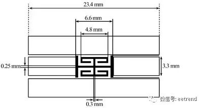
Figure 6: Structure of the FG-CPW Rectifying Diode Antenna
Figure 7: Structure of the CCRC Filter
Most research on rectifying devices focuses on operating frequencies of 2.45 GHz and 5.8 GHz. At a frequency of 35 GHz, the efficiency of the rectifying antenna and transmitter is lower, but the advantage of devices at this frequency is their smaller size and longer transmission distance. For long-distance transmission, the overall efficiency of the 35 GHz system is higher than that of the 2.45 GHz and 5.8 GHz systems for the same antenna size. Reference [6] introduces a rectifying antenna device operating at 35 GHz, with a patch antenna measuring 2.84 mm × 2.84 mm, directly fed using microstrip connections to the edge of the patch with a characteristic impedance of 50 Ω, 0.78 mm wide, and an insertion depth of 0.95 mm. The rectifying diode used is an Agilent HscH-9201 gallium arsenide Schottky barrier diode, with one end grounded and the other connected to the microstrip line. The output filter consists of a 1/4 wavelength microstrip line and a 47 pF capacitor, which allows even harmonics and DC current to pass while blocking odd harmonics. The input filter prevents DC and harmonics from flowing back to the receiving antenna. The maximum conversion efficiency of this rectifying diode antenna is 52%, with an output power of 25.6 mW.
Dual-polarized rectifying antennas have two advantages: they can double the energy received in each unit area and can receive dual-linear or single-circularly polarized signals. Additionally, using a layered design can effectively reduce the size of the rectifying antenna. Reference [7] introduces a dual-polarized layered structure slot-coupled rectifying diode antenna. This rectenna operates at 8.51 GHz, using a patch antenna as the receiving antenna, supported by lightweight foam with a relative dielectric constant of 1.07, helping to reduce unwanted surface wave modes. The substrate consists of two materials, Duroid 5880 and Sheldahl’s Novaclad G2200, with the antenna placed on top. The antenna and microstrip feeding circuit are separated, using slots or coupling slots for electromagnetic energy coupling from the feeding circuit to the patch antenna. The ground plane includes coupling slots to separate the antenna from the feeding circuit, protecting the feeding circuit from interference from incoming RF energy while also preventing harmonics excited by the diode from re-radiating. The diode circuit is placed beneath the ground plane. In this design, independent rectifying circuits are used for two vertically polarized waves, allowing the output voltage to be doubled compared to single-polarized output voltage.
In most designs of rectifying diode antennas, the structure generally consists of narrowband antennas fed by transmission lines, along with traditional matching circuits and filters. Reference [8] introduces a novel structure broadband rectifying diode antenna, as shown in Figure 8, where a logarithmic spiral line is installed at the center of a Schottky diode, with the diode size limiting the upper frequency of the broadband antenna, and the total size of the antenna limiting the lower frequency. The advantages of this logarithmic spiral structure include: a single-plane structure facilitates diode connection, can produce dual-polarized waves, and is convenient for connecting the DC output line at the top of the spiral line. Directly integrating the diode into the antenna allows the antenna to provide matching functionality while also filtering the output signal, reducing the size of the rectifying antenna and increasing the bandwidth.
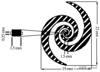
Figure 8: Structure of the Spiral Rectifying Diode Antenna
During the wireless energy transmission process, the transmitting and receiving antennas need to be precisely aligned; if not aligned correctly, the maximum output voltage will sharply decline, while traditional energy transmission and reception parts usually have narrow beam widths, making alignment difficult. Reference [9] introduces a novel bowtie-shaped reverse silicon rectifying diode antenna capable of addressing alignment issues. As shown in Figure 9, this rectifying antenna is printed on a substrate made of Rogers Duroid 5880, with a thickness of 0.7874 mm, operating at a frequency of 5.8 GHz. Its main components include two pairs of bowtie antennas fed by coplanar strips, two band-pass filters, one rectifying diode, and one load impedance. The bowtie antennas operate at a frequency of 5.8 GHz with a gain of 8.45 dBi, higher than that of rectangular antennas. This structure uses two pairs of bowtie antennas, one pair for receiving microwave energy and the other for adjusting the main beam of the antenna array to align with the energy source. Both band-pass filters are used to suppress high-order harmonics. An external 150 Ω resistor is used for testing, and when the energy density is 10 mW/cm², the output of the rectifying antenna is 2.83 V, with a conversion efficiency of 84.4%, which increases with higher energy density.
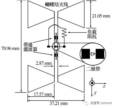
Figure 9: Geometric Structure of the Bowtie-Shaped Reverse Silicon Rectifying Diode Antenna
In most designs of rectifying antennas, a common method to increase conversion efficiency is to suppress harmonics generated by the diode, necessitating the addition of a low-pass filter between the diode and the receiving antenna. By endowing the antenna with harmonic suppression characteristics, the low-pass filter between the receiving antenna and the rectifying diode can be removed, thus reducing size and lowering costs. Reference [10] introduces a rectifying antenna using a sector antenna to suppress harmonics, where the sector angle of the microstrip sector antenna is 240°, and the feeding angle is 30°. The sector antenna effectively prevents the re-radiation of high-order harmonics at 4.8 GHz and 7.2 GHz generated by the nonlinear diode. This antenna also includes a low-pass filter between the load and the diode to block high-order harmonics from entering the load. Testing shows that the gain of the sector antenna is 4.677 dBi, effectively preventing the re-radiation of harmonics at 4.8 GHz and 7.2 GHz; when the input energy to the rectifying antenna is 10 dBm with a load of 150 Ω, the maximum conversion efficiency reaches 77.8%. Figure 10 shows the dimensions of the sector receiving antenna, and Figure 11 illustrates the structure of the rectifying antenna.
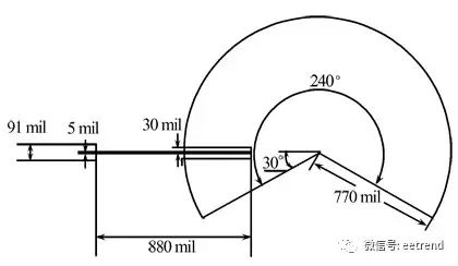
Figure 10: Dimensions of the Sector Receiving Antenna
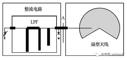
Figure 11: Structure of the Sector Rectifying Diode Antenna
3 Time Reversal Algorithm
The time reversal technique was first proposed by M. Fink in 1992, initially used for ultrasonic detection. This technique allows sound waves propagating in uniform and non-uniform media to achieve time and space synchronized focusing, enabling the detection of targets in complex media. Other techniques, such as adaptive time delay focusing methods and phase conjugation methods, have specific requirements for the location of detected targets and the characteristics of surrounding media. Using TR technology for target detection provides more degrees of freedom, allowing for high-resolution imaging of targets in more situations. TR technology has achieved certain results in ultrasound cancer detection and underwater acoustic communication.
In recent years, researchers have begun to explore the application of TR technology in the field of electromagnetic waves. It has been found that using TR technology in the propagation of electromagnetic waves can similarly achieve time and space synchronized focusing of electromagnetic waves, thus it can also be used for target detection, such as microwave imaging and medical cancer treatment, while gradually initiating research on its application in modern wireless communication systems.
The basic principle of TR technology in wireless sensor networks is to achieve wireless transmission of data through a channel transmission mode of “one-to-many” and “many-to-one.” The specific implementation can be divided into three steps: first, a shock signal is sent from the signal source to multiple surrounding sensors (“one-to-many” transmission) to establish the physical characteristics of the spatial transmission channel (or obtain the impulse response characteristics of the spatial physical channel); secondly, the surrounding sensors store the received impulse response signals hr(t); finally, the surrounding sensors send and transmit their received impulse response signals in reverse time hr(T-t) (“many-to-one” transmission), and after spatial propagation, the signals converge at the signal source, forming spatial focusing of the wireless propagation signal. Simultaneously, since the channel responses recorded by each sensor fully consider the spatial phase delays introduced by different paths and the effects brought by non-uniform media, the signals from surrounding sensors can converge spatially at one point and also arrive simultaneously, achieving focusing in both time and space. It is precisely because TR technology can achieve time-space focusing in complex electromagnetic environments that it can effectively solve issues in wireless signal transmission and self-location of signal sources in non-uniform media and dispersive media.
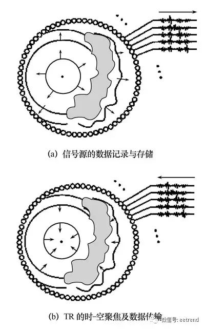
Figure 12: Time Reversal Wireless Spatial Data Transmission Process
Research on wireless sensor networks based on TR technology is still in its early stages internationally, with only Professor Richard J. Barton’s research team in the United States achieving some results. However, it can be profoundly recognized that utilizing the time reversal algorithm’s space-time focusing characteristics can address issues in wireless channel transmission, such as multipath effects, signal transmission in non-uniform media, and precise positioning of network nodes, thereby solving problems of energy supply and replenishment for sensors, as well as the security and reliability of network information transmission. The enormous application potential of TR technology in research on wireless sensor networks has yet to be discovered and recognized.
The energy issue in wireless sensor networks can be addressed by combining TR technology and rectenna technology. The rectenna in wireless sensor networks serves the dual functions of wireless communication and wireless energy transmission. Research on rectennas based on TR technology will help China seize a new high ground in the field of wireless sensor network technology research, providing a series of the latest technologies and solutions for the future design of low-cost, low-energy, high-security, reliable, and long-lasting wireless sensor network systems.
4 Conclusion
Rectenna technology and time reversal algorithms are crucial research pathways for addressing energy replenishment issues in wireless sensor network nodes. As discussed above, it is evident that the current rectifying diode antennas differ from those required by wireless sensor networks, and designing rectifying diode antennas that are small in size, lightweight, and have high conversion efficiency is the research goal for wireless energy transmission technology in wireless sensor networks.