Follow us for free subscriptions to avionics news.

Abstract
The avionics products contain a large number of memory and programmable devices, with an increasing proportion of software, making testing and maintenance of products more challenging. This research focuses on testing and software repair issues for such circuit boards from the perspective of software repair. By directly reading and replacing or porting software, the internal core code of processors, memory, configuration chips, or programmable devices on the circuit board is backed up. The core code is then disassembled, and an analysis of the assembly program principles is conducted to form a workflow diagram of the modules. Testing and fault localization of such boards are achieved through forward development.
Keywords
Disassembly; Circuit Board Testing; Software Replacement; FPGA
For traditional software to run correctly on a specific platform, it must adhere to a basic convention of that platform. This convention is not reflected in high-level language development at the upper level but must be strictly followed in low-level assembly language forward or reverse development. This convention is known as ABI (Application Binary Interface), which specifies the use of registers and the structure of the call stack. Embedded system software not only possesses all the characteristics of upper-level application software but is also closely related to hardware. The source code of embedded software, after compilation and linking, cannot run on other hardware platforms, and even on other platforms using the same processor, it cannot run. This is a direct reflection of the complexity of embedded software. In recent years, avionics products have developed rapidly, with increasing modularity, componentization, and digitization. A large number of programmable devices are integrated into the boards. During avionics maintenance, some boards lack documentation, making it difficult to understand the working principles and workflows of the boards based on hardware understanding. This paper proposes a method to organize the workflow of embedded boards using disassembly.

1 Research on Disassembly Methods
Using IDA software from chip companies to read and back up the online software code of the circuit board, and using decompilation tools to decompile the software code to obtain the corresponding assembly files for each module. The assembly files are analyzed, focusing on the initialization of modules, data flow, and hardware space address allocation, forming data flow diagrams and module block diagrams.
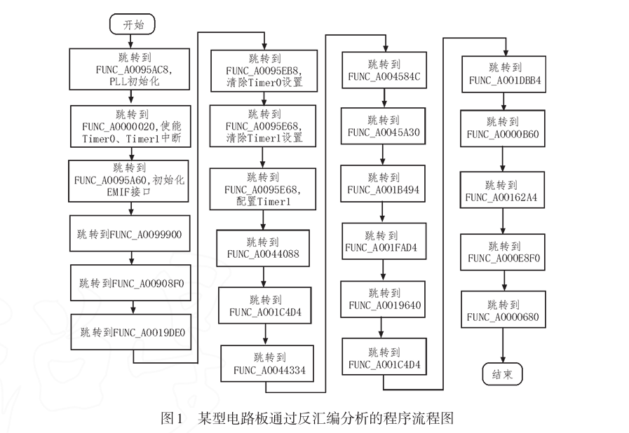
1.1 Forming Data Flow
Analyze the data interaction process between the decompiled assembly files, chips, and peripherals, and combine it with hardware space addresses to form the boot startup process and data interaction process between modules. The data flow analyzed after decompiling a certain type of circuit board is shown in Figure 1.
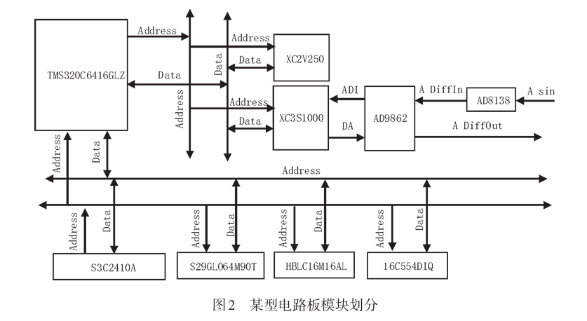
1.2 Module Division
Combining hardware space address allocation and the boot startup process, the general module division of the embedded board is analyzed. The situation after division for a certain type of circuit board under test is shown in Figure 2.
2 Test Hardware Design
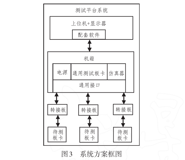
The test platform system provides a general platform for signal detection, signal excitation and simulation, power supply, etc., for the board under test, providing a general test board and an appropriate adapter board.
The chassis integrates power supply, general test board, and simulator. The power supply uses Changfeng’s DC power supply, providing ±12V and ±5V voltages. The test board provides resources such as GPIO, general test ports, serial ports, LVDS, programmable clocks, ADC, DAC, and VGA interfaces. The simulator provides Xilinx-FPGA/CPLD, TI-DSP, and ADI-ARM simulators. The scheme block diagram is shown in Figure 3.
2.1 Board Scheme
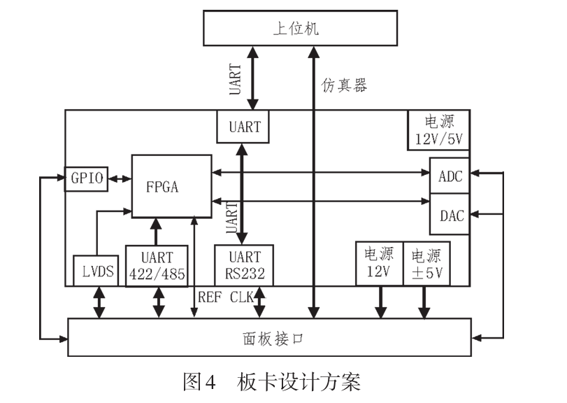
The general test board provides the under-test board with matching GPIO, serial ports, clocks, LVDS, AD/DA, etc., concentrating common serial, USB, and LVDS interfaces on the board and matching them with the test module through an adapter board. The board design scheme is shown in Figure 4.
2.2 Test Mainboard Hardware Design
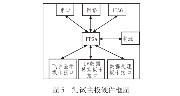
The hardware design block diagram of the test mainboard is shown in Figure 5.
2.2.1 FPGA Chip
The main FPGA is XC7K325T-2FFG900I.
2.2.2 Power Supply Design
The power supply chip uses ADI’s LTM4644, which converts 5V voltage into 1.0V, 1.8V, and 3.3V. LTM4644 is a four-channel DC/DC buck-type μModule regulator with a single output of 4A, containing a switch controller, power FET, inductor, and supporting components. It supports an output voltage range of 0.6V to 5.5V within an input voltage range of 4V to 14V or 2.375V to 14V.
2.2.3 Network Module Design
The network chip uses the W5300 chip, which is a 0.18μm CMOS technology chip with a built-in 10/100 Ethernet controller and integrated TCP/IP protocol. The W5300 is designed for easy implementation of Internet embedded applications, featuring high stability, high performance, and low cost.
2.2.4 Serial Port
The serial port uses MAX3232EUE and MAX490ESA chips.
2.2.5 A/D and D/A Circuit Design
The analog-to-digital conversion chip uses AD9430BSVZ, and the digital-to-analog conversion chip uses AD9753AST, with a clock of 60MHz.
3 Test Software Design
3.1 Upper Computer Software Design
3.1.1 Testing Function
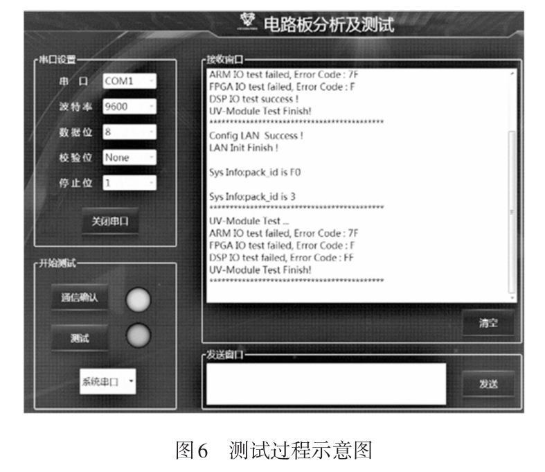
The upper computer software provides corresponding operation buttons, allowing users to click to test the corresponding parts of the board. If the test is successful, the indicator light at the corresponding test button will indicate as required. Similarly, if there is an issue, the indicator light will signal, and the corresponding upper computer software interface will print information for the user to view. The testing process is illustrated in Figure 6.
3.1.2 Testing Principle
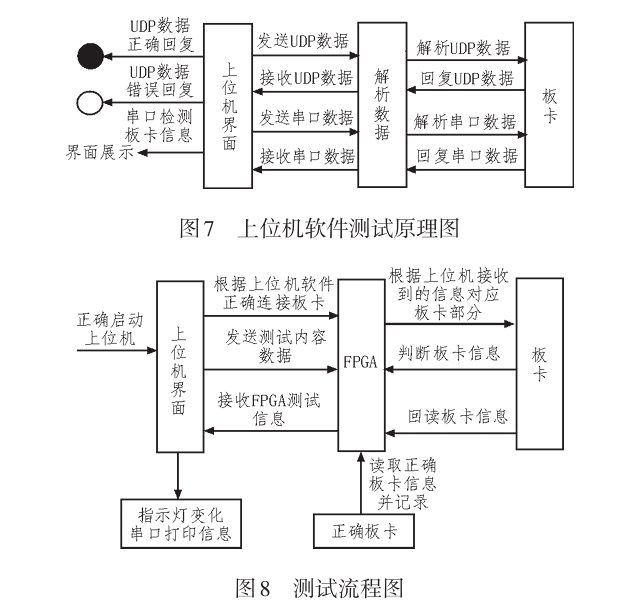
Information exchange between the upper computer software and the board is achieved through UDP network and RS232 serial communication, reading information from the board according to the agreed protocol message. The sending end of the upper computer software classifies the information for network communication and the board information to be tested, allowing focused testing on specific parts. The testing principle of the upper computer software is shown in Figure 7, and the testing process is shown in Figure 8.
3.1.3 Communication Principle
Information exchange between the upper computer software and the board is conducted through UDP network, defining protocol messages that include IP and port. The message corresponds to different parts of the board based on the sending identification number. After receiving the corresponding information, the board replies to the upper computer. The upper computer compares the reply instruction with the previous protocol message; if there is a discrepancy, a red light will illuminate, and if they match, it indicates the board is functioning normally, lighting a green light.
In the event of a board failure, communication between the upper computer software and the board occurs via RS232 serial communication. Based on the agreed serial number, baud rate, data bits, parity bits, and stop bits, communication with the board is completed. When the serial port is opened, the board replies with connection status information. During board testing, the serial sender transmits a specific number (as agreed with the board) to complete the status detection of a specific part of the board. The board will respond to the upper computer’s serial port with the status information after the detection is complete, which is displayed on the upper computer software interface, allowing the operator to take appropriate action based on the information read by the upper computer.
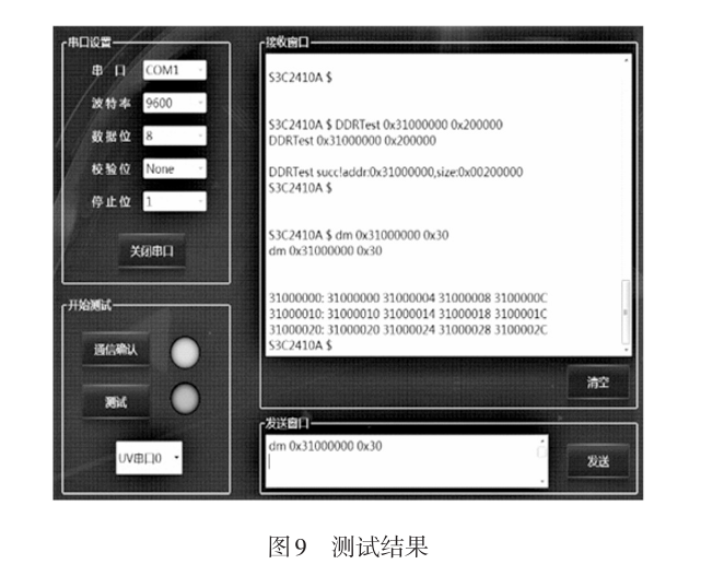
3.1.4 Testing Results
Based on the results of the upper computer testing, the operator can effectively detect the status information of the tested board and quickly address any issues present. The FPGA compares the correct board information with the information of the board under test, and the final testing results are visually displayed on the upper computer software interface. The operator can record the issues encountered and the symptoms of errors based on the testing results, as shown in Figure 9.
3.2 Lower Computer Testing Software Design
3.2.1 Communication Confirmation Design
The FPGA chip serves to receive commands from the upper computer. Data exchange between the upper computer and FPGA uses the UDP protocol, with a custom message format. First, a connection is established, where the upper computer sends a query code to the test mainboard, and the test mainboard replies with a specific character to the upper computer. If the upper computer receives it correctly, it indicates that the connection is established. Upon clicking the communication confirmation, the upper computer sends a communication confirmation character, and the test mainboard prints the character code to the system serial port upon receipt. For different board interfaces, clicking the option to switch serial port commands will cause the test mainboard to switch the serial connection to the corresponding board interface. If the board connection is incorrect, garbled characters will appear.
3.2.2 Serial Port Switching Design
The test mainboard receives the command to switch the serial port from the upper computer via the network. The test mainboard switches the serial line connected to the upper computer to the serial line specified by the network packet based on the serial number in the data packet.
4 Conclusion
This paper selects three typical boards from a certain type of aircraft and uses direct online reading, replacement, or software porting methods to back up the internal core code of processors, memory, configuration chips, and programmable logic devices on the circuit board. It also conducts analysis on some assembly programs to understand the principles of modules in working status. Finally, through forward development, testing and fault localization of this type of board is achieved, providing certain reference value for testing complex airborne circuit boards.
(This article is selected from “Electronic Design Engineering” by authors Yuan Rong, Liu Liangyong, and Li Jinmeng, from the State-owned Wuhu Machinery Factory. This article is reproduced solely for the purpose of knowledge dissemination. If there are any copyright issues, please contact us promptly!)