When using Xilinx Aurora 8b10b IP, the following issue occurs as shown in the figure below:
-
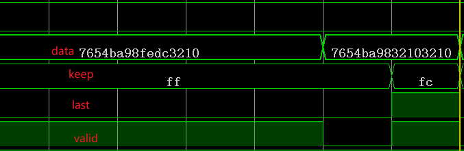
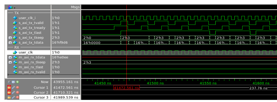
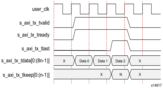
In frame mode, under the condition of 2 lanes at 1Gbps rate, when sending the last data, one clock is pulled low, then last is pulled high, but keep is missing one bit, resulting in a loss of one byte of data;
-
In frame mode, under the condition of 1 lane at 1Gbps rate, it works completely normally;
-
What kind of problem could cause this?
Operating Principle
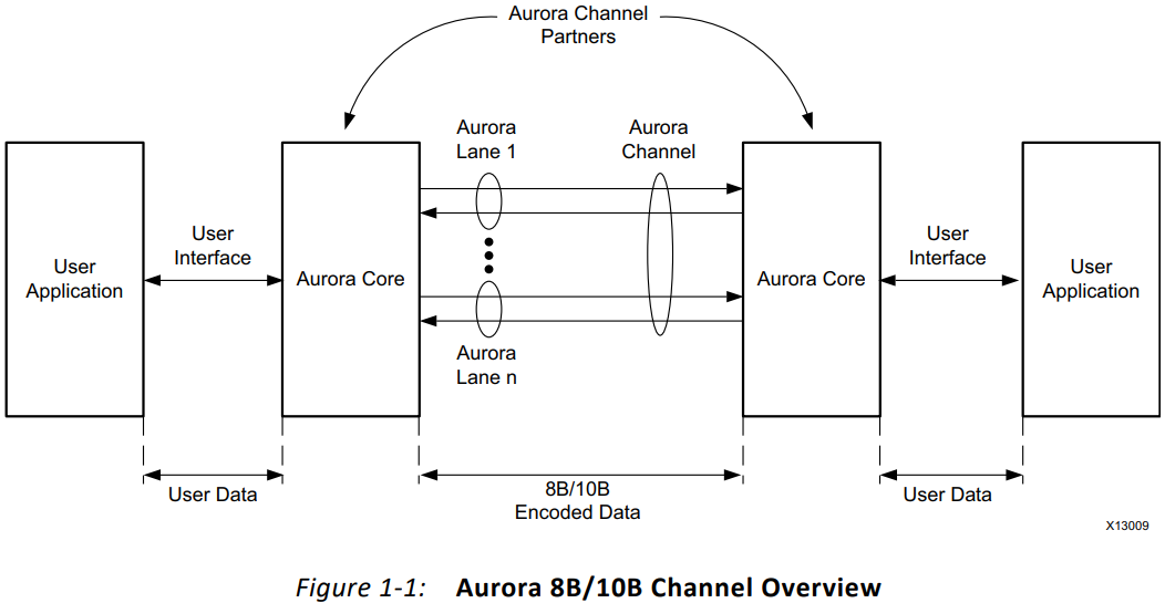
First, regarding the operating principle of the Aurora 8b10b IP core, it can choose between frame or stream modes (corresponding to framing or streaming interface). This time, we focus on the data transmission mechanism in frame mode. The Aurora protocol uses multiple channels (lanes) to transmit data, where the data width of each channel may differ but is usually byte-based, combined with keep and last signals to indicate valid data bytes and the end of the frame.
In frame mode, the data bus width of the User interface can vary based on the number of lanes. For example, with 1 lane, the data width can be configured to 2 bytes (16 bits, Xilinx also allows configuration to 4 bytes), while with 2 lanes, the data width may expand to 4 bytes (32 bits, Xilinx also allows configuration to 2 bytes). Each byte corresponds to a keep signal bit, which indicates whether that byte is valid. The last signal marks the end of the frame.
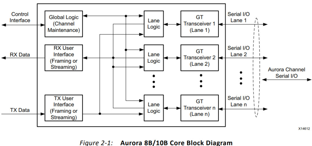
The issue arises in the case of 2 lanes, where when sending the last data, last is correctly pulled high, but the keep signal is missing one bit, resulting in a loss of one byte of data. In the case of 1 lane, it works normally. This indicates that the problem may be related to data alignment, keep signal generation logic, and constraints in the case of multiple lanes. Let’s first look at the IP’s ports:
Ports
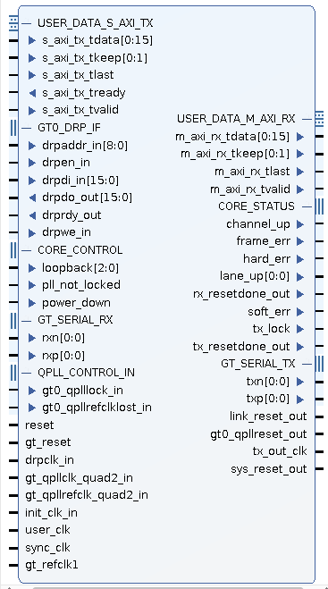
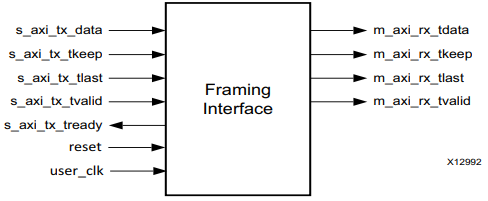
Framing interface: This time we are using Frame mode
The ideal waveform should be as follows:
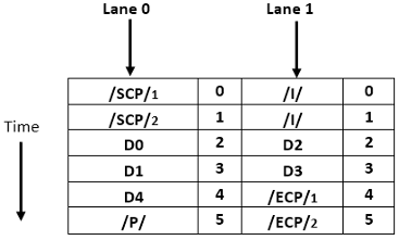
Aurora 8B/10B Frame Structure
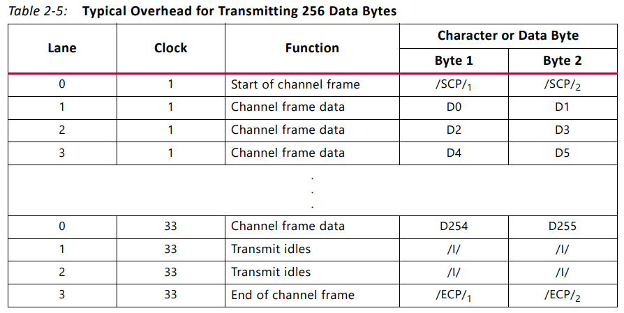
The TX submodule converts each received user frame into an Aurora 8B/10B frame through the TX interface. The start of the frame (SOF) is indicated by adding a 2-byte SCP code group at the beginning of the frame. The end of the frame (EOF) is indicated by adding a 2-byte ECP code group at the end of the frame. Whenever data is unavailable, idle code groups are inserted. Code groups are byte pairs encoded in 8B/10B, and all data is sent as code groups, so user frames with an odd number of bytes append a control character called PAD at the end of the frame to fill the final code group. Table 2-3 shows a typical Aurora 8B/10B frame with an even number of data bytes.

Byte transmission schematic in the case of dual lanes:
Terminology:
PDU: Protocol Data Unit
SCP: Start of Channel PDU, 2 Bytes Size
ECP: End of Channel PDU, 2 Bytes Size
SOF: Start of Frame
EOF: End of Frame
PAD: pad byte
TX Sending Data
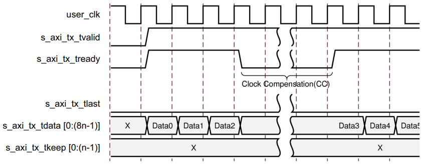
Since clock compensation is required for every lane every 10,000 bytes (2 bytes per lane design corresponds to 5,000 clocks; 4 bytes per lane design corresponds to 2,500 clocks). This means that data cannot be continuously transmitted or received. During clock compensation, data transmission will pause for six or three clock cycles.
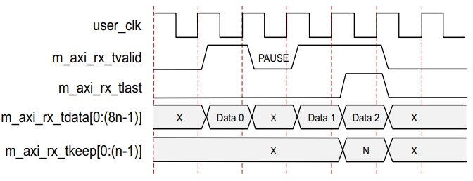
RX Receiving Data
Possible Causes
With the above basic concepts, we continue to analyze the possible causes.
1)Data length alignment issue
In the case of 2 lanes, the data bus width is larger (e.g., 32 bits), and the number of bytes in the sent data frame may not be correctly aligned, leading to incorrect generation of the keep signal in the last cycle.
For example, check whether the number of bytes in the sent data frame in the case of 2 lanes is a multiple of 4. If not, then the keep signal for the last cycle needs to be correctly set based on the remaining byte count. For instance, if there are a total of 5 bytes, under a 32-bit (4-byte) bus, the second cycle transmits 1 byte, and keep should be 0x0001 (i.e., least significant bit valid). If incorrectly set to 0x0003 (i.e., two bits valid), it may send an invalid byte, or if set to 0x0000, data may be lost.
2)Keep signal generation logic error
When generating the keep signal, the corresponding bits are not correctly set based on the actual remaining byte count, especially in the case of multiple lanes, where calculation errors lead to a missing valid bit.
Check the sending logic code, especially the part that generates keep and last. For example, in VHDL or Verilog, when detecting that the remaining byte count is less than the bus width, how to set each bit of keep. For instance, in the case of 2 lanes, assuming the data bus is 32 bits (4 bytes), when the remaining byte count is 3, keep should be 4’b1110 (high bit first) or 4’b0111 (low bit first), depending on the byte order. If there is a logic error here, it may lead to a missing bit. Generally, using Xilinx IP solutions should not have this issue.
3)Timing or synchronization issues
When generating last and keep signals, there may be timing issues that cause the signals to be out of sync, but this situation may be more complex.
4)IP core configuration error
For example, in the case of 2 lanes, if the data bus width is configured incorrectly, it may lead to the generated keep signal not matching the expected width of the IP core.
Check the configuration of the Aurora IP core to ensure that the number of lanes and the corresponding data bus width are correct. For example, for 2 lanes, if the line speed of each lane is 1Gbps, then the data rate of each lane is 1Gbps, and the actual data rate of 8b10b encoding is 1Gbps * 8/10 = 800Mbps per lane. Therefore, the total data rate is 800Mbps multiplied by 2, which is 1.6Gbps. The corresponding interface clock is 100 MHz (transmitting 16 bits per clock cycle, i.e., 2 bytes for 1 lane) or a higher frequency. However, the specific data width needs to be determined based on the IP core configuration.
5)Data packing issues
For example, when the number of bytes in the data frame is not a multiple of 4 in the case of 2 lanes, the last transmission cycle will have some valid bytes, and the low bits of the keep signal need to be set correctly. For instance, if the data length is 5 bytes, then in 2 lanes (32 bits, 4 bytes/cycle), two cycles are needed: the first cycle transmits 4 bytes (keep=0xF), and the second cycle transmits 1 byte (keep=0x1), while pulling last high. If in this case, keep is incorrectly set to 0x0 (i.e., only high bits valid), or if one byte is missed in processing, it may lead to issues. Generally, using Xilinx IP solutions should not have this issue.
6)Errors in calculating valid data bytes
For example, in the case of 1 lane, the remaining byte count may be correctly calculated, and the corresponding keep signal set, but in the case of 2 lanes, the calculation may be incorrect, leading to a missing bit in the keep signal for the last cycle.
Check whether the last data is sent correctly with the last signal pulled high in the same clock cycle, and that the data remains valid. For instance, in the last cycle, the data must be valid, last pulled high, and keep correctly indicating valid bytes. If last is pulled high a cycle early, or if last is pulled high when the data is invalid, it may lead to issues.
7)Errors in physical constraints
For example, in the case of 1 lane, there are no order issues with rx/tx; but in the case of 2 lanes, there may be order issues with rx/tx, and if constraints are not correctly implemented, it may lead to encoding confusion at the receiving end.
Solutions
1. Ensure that when sending data, the data length is correctly aligned in the case of 2 lanes, or if alignment is not possible, correctly calculate the valid byte count for the last cycle and set the corresponding keep signal.
2. Check the logic for generating the keep signal to ensure that in the last cycle, each bit is correctly set based on the remaining byte count. For instance, if there are 3 remaining bytes, then 3 of the 4 bits of keep should be set high, depending on the byte order.
3. Verify the configuration of the Aurora IP core to ensure that the number of lanes and data bus width match, for example, whether the data width for 2 lanes is 32 bits.
4. Check the timing to ensure that the last and keep signals are synchronized with the data and that there are no timing issues causing the signals to be incorrectly sampled.
5. Check the constraints to ensure that physical constraints are correct.
Verification Steps
-
Simulation testing: Simulate the sending logic in 2 lanes mode in Vivado, checking whether the keep and last signals of the last frame meet expectations, especially focusing on cases where the remaining byte count is not a multiple of 4.
-
Protocol analyzer packet capture: Use ILA (Integrated Logic Analyzer) to capture the sending end interface signals, confirming whether the generated
<span>keep</span>and<span>last</span>signals match the design. -
Code review: Check the logic for generating the
<span>keep</span>signal in the sending logic, confirming that its dynamic calculation covers all possible remaining byte scenarios (1/2/3 bytes).
Problem Resolution