Abstract:
The pulse generator is widely used in power electronics, motion control, vehicle control, and other applications. It is a fundamental and versatile component for device driving and control. However, the current pulse generator has weak network communication capabilities, which cannot meet high-speed control demands and is difficult to integrate into intelligent manufacturing systems. To address this issue, a pulse signal generator based on real-time industrial Ethernet EtherCAT and Loongson LS1C processor has been designed. It achieves high-speed and real-time communication through EtherCAT and can be flexibly configured into chain and ring topologies. The pulse signal generator can operate in four working modes to meet various control requirements. Finally, experiments were conducted to test the working modes and accuracy of the pulse generator.
Chinese Citation Format: Lin Hao, Han Qingmin, Song Dong, et al. Pulse generator with real-time industrial ethernet[J]. Application of Electronic Technique, 2018, 44(10): 64-67, 72.English Citation Format: Lin Hao, Han Qingmin, Song Dong, et al. Pulse generator with real-time industrial ethernet[J]. Application of Electronic Technique, 2018, 44(10): 64-67, 72.
0 Introduction
The pulse generator is an instrument widely used in fields such as power electronics, industrial control, and robotics[1-3]. Pulse generators are typically designed using analog circuits and microprocessors. Reference [2] proposed a PWM isolation dimming circuit and LED dimming driver power supply based on operational amplifiers, transistors, and other discrete analog devices. Reference [4] introduced a development plan for PWM signals with controllable output frequency and duty cycle based on the enhanced timer of the HCS12 microcontroller, solving the problem of insufficient PWM output channels due to hardware limitations. Reference [5] designed a general-purpose dead-time configurable PWM signal generator based on embedded SoC, achieving flexible control strategy configuration. The circuit built with discrete analog devices generates PWM signals, which involves many components and is complex, making debugging difficult. When PWM signals are generated by microprocessors or SoCs, the microprocessor can meet the requirements when the signal channels are few; however, when the number of PWM signals exceeds four, significant delays occur due to the sequential execution of processor instructions, leading to unstable PWM signal waveforms[3]. Therefore, FPGAs can be used to design PWM signal generators since FPGA instructions are executed in parallel, and increasing signal channels does not affect the speed and stability of the pulse signals, thus achieving high-precision control[6]. References [3] and [7] utilized FPGAs to design devices capable of simultaneously outputting multiple PWM signals for different applications. The aforementioned pulse signal generators can only operate independently and cannot be connected to the field control system via a bus network for flexible and rapid configuration. Hence, reference [8] proposed a method and device for pulse signal output based on CAN, which updates the PWM output frequency and duty cycle through CAN messages. However, CAN bus communication rates are relatively slow, making it difficult to apply in high-speed control scenarios.
With the advancement of Industry 4.0 and intelligent manufacturing, networked, intelligent, and digital industrial internet systems are becoming increasingly widespread[9], posing new application requirements for basic control devices. Traditional standalone pulse generators or bus-based pulse generators cannot meet the high-speed communication and rapid response requirements of the industrial internet. To address this issue, this paper designs a pulse signal generator based on high-speed real-time industrial Ethernet, utilizing EtherCAT for communication between devices and external control systems, thereby enabling high-speed data exchange and stable control.
1 System Design
The pulse generator provides pulse control signals for field devices in industrial control, as shown in the block diagram in Figure 1. Given the high real-time requirements of industrial control devices, this paper selects real-time Ethernet EtherCAT for communication. EtherCAT is an open architecture fieldbus system based on Ethernet, characterized by strong real-time performance, flexible topology, high synchronization accuracy, cable redundancy, and functional safety protocol capabilities. The pulse generator includes a microprocessor minimum system, EtherCAT communication controller, EtherCAT communication interface, optocoupler (hereinafter referred to as opto-isolator), solid-state power relay, and field signal interface. The EtherCAT communication controller receives command signals through the EtherCAT communication interface, parses the command signals, and generates parsed signals; the microprocessor configures the output mode of the pulse signal based on the parsed signals and outputs pulse signals according to the corresponding mode. The pulse signals are electrically isolated by the opto-isolator before being output to the solid-state power relay; the solid-state power relay enhances the load capacity of the pulse signals, and the output pulse signals are sent to field devices via the field signal interface.
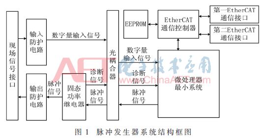
The pulse generator uses the EtherCAT bus to communicate with the host through the EtherCAT communication controller, which implements the medium access control function of EtherCAT communication and is responsible for processing EtherCAT data frames to enable data exchange between EtherCAT master and slave applications. The microprocessor performs logical calculations, coordination control, and other functions for the pulse output card.
The EtherCAT communication controller and communication interface of the pulse generator include two types: MII interface and EBUS interface. When using the MII interface, the EtherCAT communication controller connects to the PHY chip through the MII interface and communicates with the external device through the RJ45 interface. When using the EBUS interface, the EtherCAT communication controller communicates directly with the external device through the EBUS bus.
The solid-state power relay can protect the output circuit, including overheat protection, short circuit protection, and outputs diagnostic signals to the microprocessor. The diagnostic signals are electrically isolated by the opto-isolator before being input to the microprocessor, thus enabling the diagnostic function of the output circuit and improving the reliability of the pulse generator’s operation. The pulse signals output by the solid-state power relay are sent to field devices through the field signal interface after passing through the output protection circuit.
2 Hardware Design
2.1 Minimum CPU System
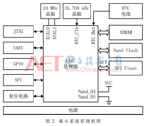
Based on the factors of device autonomy and control, the pulse signal generator uses the Loongson processor LS1C0300A, which is based on the GS232 processor core and provides rich peripheral interfaces. The minimum system circuit diagram using LS1C is shown in Figure 2 and includes power supply, debug port JTAG, serial port UART, memory SDRAM, NAND Flash, SPI Flash, serial communication SPI interface, reset circuit, and general GPIO interfaces. The SPI interface connects to the EtherCAT slave controller ET1100; GPIO connects to the pulse output circuit and diagnostic circuit, controlling the alarm circuit to implement alarm functions in case of faults. The LS1C integrates RTC functionality, thus when the RTC_Clk pin is connected to an external clock source of 32.768 kHz crystal oscillator, and a RTC battery is provided to maintain accurate timing during power outages. SDRAM is connected to LS1C via a parallel bus for storing data during processor operation and loaded programs. LS1C supports multiple boot modes, and the corresponding pins are configured to select the boot mode. In this design, the NAND_D4 and NAND_D5 pins are connected to high and low levels, respectively, setting LS1C to boot from SPI Flash and load the PMON boot system.
2.2 EtherCAT Communication Circuit
The EtherCAT communication circuit implements the sending and receiving functions of EtherCAT signals, as shown in Figure 3, which includes ET1100, PHY, EEPROM, clock, network transformer, RJ45 interface, and other components. ET1100 is a dedicated chip that implements the EtherCAT data link layer protocol, processes EtherCAT data frames, and provides data interfaces for slave control devices. ET1100 receives EtherCAT messages through PHY_0, extracts command data sent to itself from the messages and stores it in the internal storage area, and writes local data from the internal storage area into the corresponding sub-messages to achieve data exchange between external commands and local data of the slave. Then, ET1100 sends the EtherCAT messages to the next device through PHY_1.
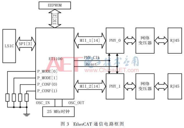
The EEPROM memory is connected to the EtherCAT communication controller via the IIC bus. ET1100 communicates with the EEPROM through the IIC interface, and the EEPROM stores the device configuration information of ET1100. ET1100 connects two MII interfaces and outputs clock signal PHY_Clk and reset signal Reset to the PHY device. To reduce processing and forwarding delays, ET1100 has undergone optimized design for the MII interface, imposing constraints on the selection of PHY chips[10]. In this design, the MICREL company’s KSZ8051MLL is selected. The configuration pins of ET1100 are multiplexed with the MII pins; to clarify the working mode of this circuit, the key configuration pins are separately shown in Figure 3, connecting P_MODE[0] and P_MODE[1] pins to ground to select ET1100’s port 0 and port 1, and connecting P_CONF(0) and P_CONF(1) pins to ground to set ports 0 and 1 to use MII interface for communication with the PHY chip.
2.3 Output Driver Circuit
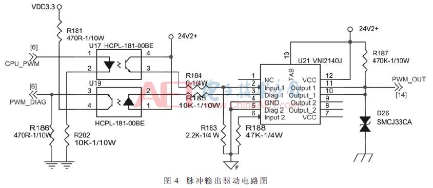
The pulse output circuit includes optocouplers, driver circuits, and protection circuits, as shown in Figure 4. The optocoupler provides electrical isolation between field devices and internal circuits. The driver circuit amplifies the power of the pulse signals, using the ST company’s compact high-performance industrial solid-state power relay VNI2140J, which can achieve an output current of 1 A per channel, meeting industrial requirements. The VNI2140J has built-in load disconnection protection, providing independent active current limiting for each output, preventing system power supply voltage drop due to load failure, and offering ground failure protection and diagnostic functions. When the load is excessive or a short circuit occurs, the power relay outputs a diagnostic signal, which is fed back to the CPU chip through the optocoupler to implement fault diagnosis functions.
3 Software Design
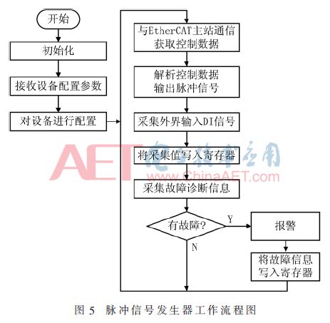
The workflow of the pulse signal generator is shown in Figure 5. After the system is powered on, it first initializes the system, including UART, SPI, general timers, GPIO, ET1100, Flash, SDRAM, and other peripherals. It then receives configuration parameters from the device through ET1100, including working modes, timing base, cycle, and other parameters; the processor sets the device based on the configuration parameters, receives control data from the EtherCAT master station, including duty cycle, cycle, delay, etc., parses and calculates it, and outputs the corresponding pulse signals. While outputting signals, the device collects fault information, and if a fault occurs, the device processes the alarm and writes the alarm data into registers and EtherCAT messages.
The parameters set by the master station include working modes, duty cycle, timing base, delay, cycle, and other parameters. The duty cycle indicates the proportion of the high-level duration of the output pulse signal to the pulse cycle; the cycle indicates the frequency of the output pulse signal; the timing base indicates the minimum time resolution of the pulse signal; the delay indicates that the pulse signal is output after a specified delay when the signal is enabled.
The working mode determines the pulse signal output mode of the device, which includes four working modes: pulse output mode, pulse-width modulation (PWM) mode, pulse train mode, and delay mode. The pulse output mode allows the pulse generator to output a specified amplitude and high-level duration pulse, with the remaining time being low-level. The PWM mode allows the pulse generator to continuously output pulse signals, with fixed pulse amplitude and cycle, and the high-level duration of the pulse can be automatically adjusted based on the received EtherCAT signals. The pulse train mode allows the pulse generator to output a specified number of pulses, with pulse amplitude, cycle, and high-level duration specified in the received EtherCAT signals. The delay mode outputs the corresponding pulse signal after a specified delay when the digital input signal received by the pulse generator changes (including rising or falling edges), where the way the digital input signal changes, delay time, and output pulse signal type are determined by the EtherCAT message data received by the pulse generator. Through these four working modes, the pulse generator can meet the working requirements of different field devices.
4 Network Topology
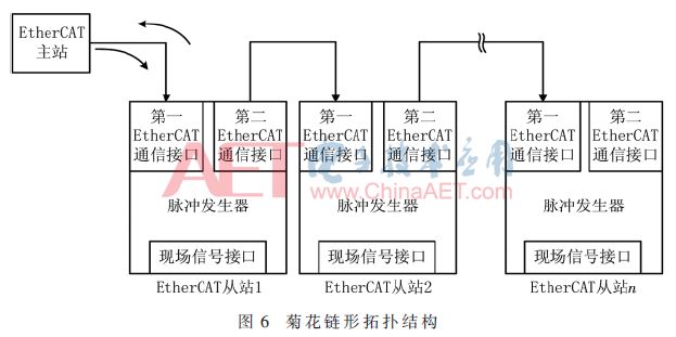
The pulse signal generator has two EtherCAT communication interfaces, allowing multiple pulse generators to be networked into a system via the EtherCAT communication interfaces, thereby expanding the pulse signal output channels. Each pulse generator serves as an EtherCAT slave. The networking methods include daisy chain and ring topologies, as shown in Figures 6 and 7.
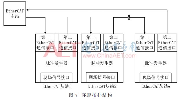
When multiple pulse generators form a ring network, if any device in the network fails or a link is broken, the EtherCAT master can access the remaining pulse signal generators through both ends of the ring, thus improving the reliability of the system.
5 Experiments
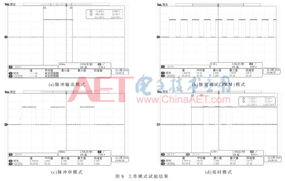
This paper designs a pulse signal generator based on real-time industrial Ethernet EtherCAT, which has four working modes, each of which is tested, and the results are shown in Figure 8. Among them, Figure (a) shows the test results of the pulse output mode, outputting a 1 s high-level signal, with the remaining time being low-level; Figure (b) shows the test results of the pulse-width modulation (PWM) mode, outputting a pulse signal with a cycle of 1 s and a duty cycle of 60%; Figure (c) shows the test results of the pulse train mode, outputting three pulses with a cycle of 1 s and a duty cycle of 60%; Figure (d) shows the test results of the delay mode, where channel 2 collects a high-level signal and channel 1 collects a pulse signal. It can be observed that after 1 s of high-level, the pulse signal generator produces three pulse signals with a cycle of 1 s and a duty cycle of 50%. The experimental results indicate that the designed pulse signal generator can generate pulse signals in four modes according to the configuration from the master station.
6 Conclusion
This paper addresses the weak communication capabilities of traditional pulse signal generators and designs a pulse signal generator with high-speed communication capabilities based on real-time industrial Ethernet EtherCAT and Loongson LS1C processor. The designed pulse generator features four working modes, which can be applied in various scenarios such as robotic motion control, vehicle control, power electronics, and industrial control.
References
[1] Qi Yue, Yang Geng, Dou Yaxuan, et al. PWM control of multi-level hybrid inverter circuit and topology analysis[J]. Journal of Electrical Engineering, 2003, 18(2): 13-17, 26.
[2] Zhong Shaoqiang. PWM isolation dimming circuit and LED dimming driver power supply: China, 201610819177.3[P]. 2016-09-12.
[3] Fan Qifu, Zhang Wenfeng, Wen Chao. Implementation of multifunctional multi-channel servo controller based on FPGA[J]. Control Engineering, 2008, 15(6): 696-698.
[4] Feng Daoning, Liu Zhaodu, Ye Yang. Design of three PWM waveform generators based on HCS12 timer[J]. Journal of Wuhan University of Technology, 2012, 34(2): 140-143.
[5] Zhang Yueling, Wang Jian, Zhao Zhonghui, et al. A general-purpose dead-time configurable PWM waveform generation circuit in an embedded SOC system: China, 201610842367.7[P]. 2016-09-22.
[6] POORANI S, URMILAPRIYA T, KUMAR K, et al. FPGA based fuzzy logic controller for electric vehicle[J]. The Institution of Engineers, 2005, 45(5): 1-14.
[7] Yang Xiaofeng, Li Yaoqian, Zheng Qionglin, et al. Comparison of PWM pulse schemes for modular multi-level converters based on DSP-FPGA[J]. Journal of Beijing Jiaotong University, 2015, 39(5): 61-68.
[8] He Dandan, Ji Lijun, Zhang Jinming, et al. A signal output method and device: China, 201710134107.9[P]. 2017-03-08.
[9] Industrial Internet Consortium. Industrial Internet Framework[R]. 2016.
[10] Beckhoff, EtherCAT slave controller ET1100 hardware data sheet[Z]. 2010.
Author Information:
Lin Hao, Han Qingmin, Song Dong, Chen Hai
(China Electronics Corporation Sixth Research Institute, Beijing 100083)
Recruitment Information