Table of Contents
1. Introduction to Basic Logic Gates and NAND Gates in Digital Circuits
1.1 Truth Table for NAND Gate
1.2 Logic Expression for NAND Gate
1.3 Symbol for NAND Gate
2. Simulating NAND Gates Using Discrete Components in Proteus
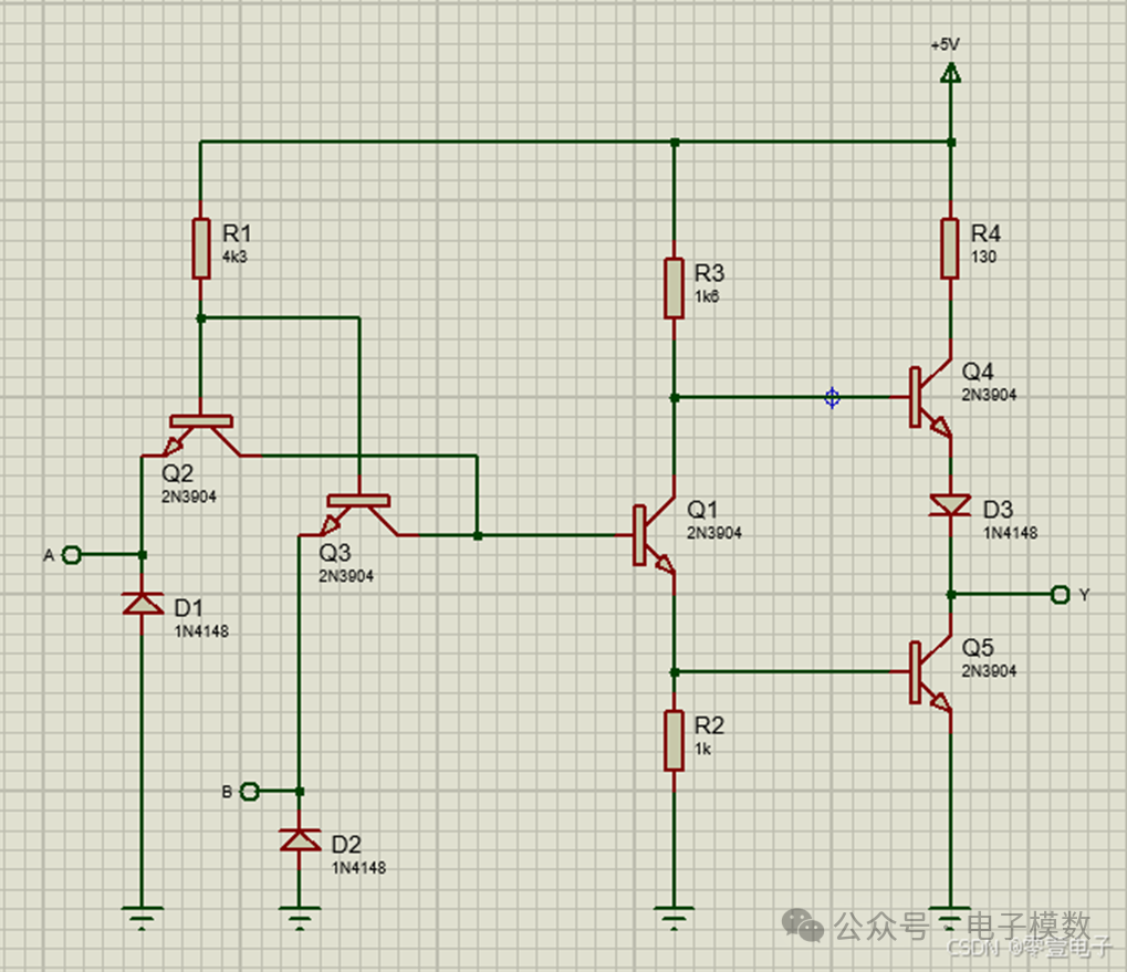
2.1 Schematic Diagram of Classic TTL NAND Gate
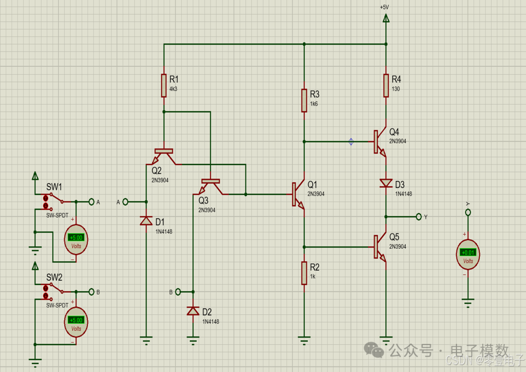
2.2 Simulation Result Images
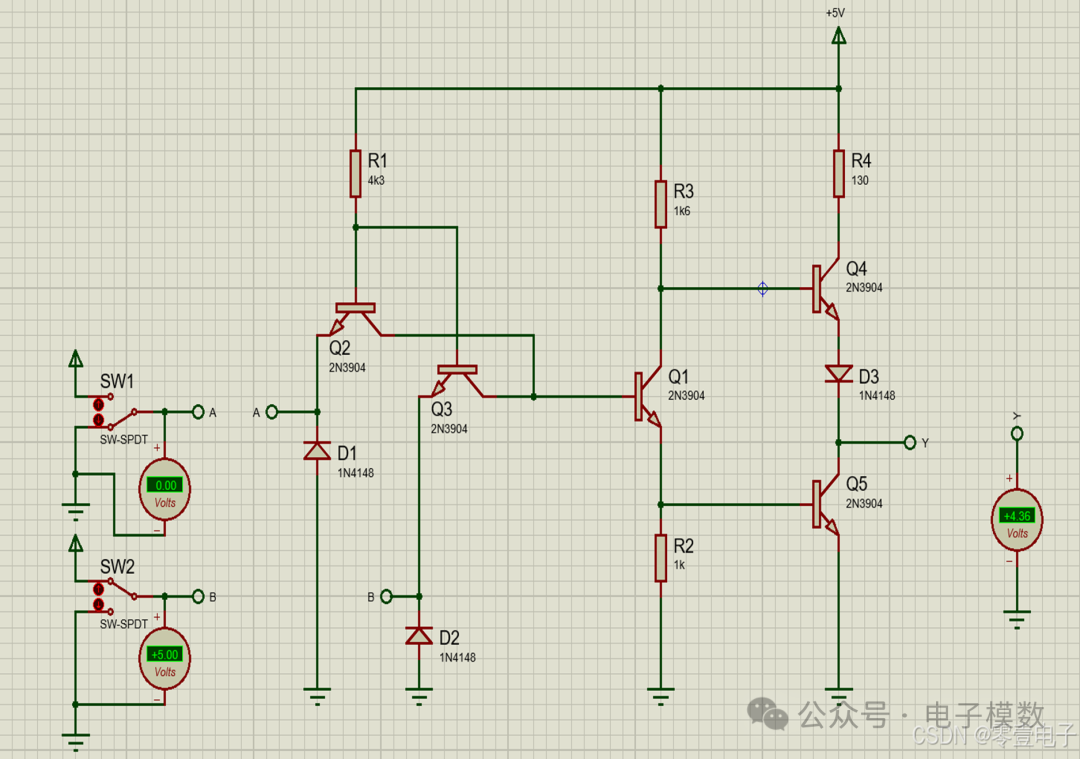
A and B both input high level 5V
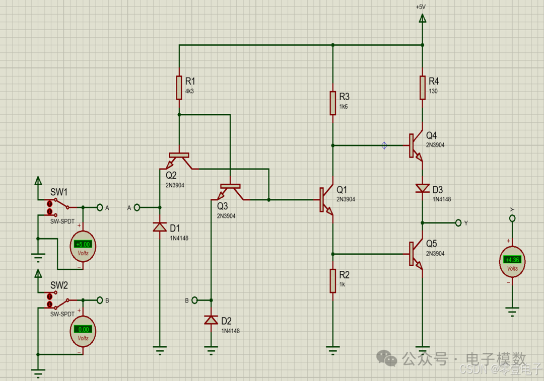
A inputs high level, B inputs low level
A inputs low level, B inputs high level
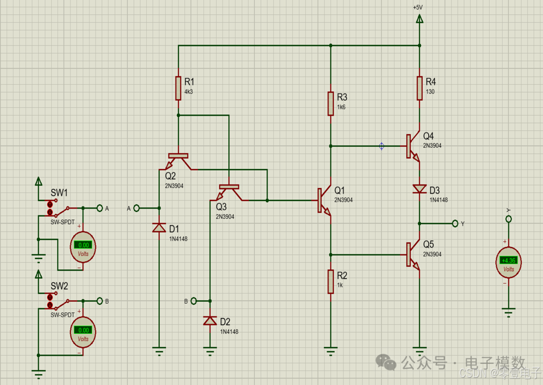
A and B both input low level 0V
1. Introduction to Basic Logic Gates and NAND Gates in Digital Circuits
NAND gates are widely used in digital circuits, taking the 2-input NAND gate as an example.
1.1 Truth Table for NAND Gate
| Logic Input A | Logic Input B | Logic Output Y |
|---|---|---|
| 0 | 0 | 1 |
| 0 | 1 | 1 |
| 1 | 0 | 1 |
| 1 | 1 | 0 |
As shown in the table, the logic of the NAND gate can be remembered with the following mnemonic: If false is present, then true; if all true, then false. (The first part means that if any input is Boolean false, the output will be Boolean true; the second part means that only when all inputs are Boolean true will the output be Boolean false).
1.2 Logic Expression for NAND Gate

In the above expression, Y represents the logic output, and A and B are the two logic input terminals.
1.3 Symbol for NAND Gate
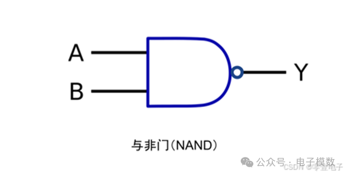
Currently, most versions of textbooks show the symbol for the NAND gate as shown in the image above.
2. Simulating NAND Gates Using Discrete Components in Proteus
Although we have already performed numerical logic operations for NAND gates, sometimes we may not have NAND gate components on hand, and it is impractical to purchase a single NAND gate component. In such cases, using existing discrete components to build a NAND gate is a convenient method. We will first use discrete diodes, transistors, and resistors to build a TTL NAND gate for simulation.
2.1 Schematic Diagram of Classic TTL NAND Gate
2.2 Simulation Result Images
A and B both input high level 5V
 A inputs high level, B inputs low level
 A inputs low level, B inputs high level
 A and B both input low level 0V
 Thank you for reading. If you have circuits related to analog or digital electronics that need analysis, please comment, and I will share as much as possible.