
Knowledge Cool Pro 👆Learn about the display industryFind Xiao Ku! Article No. 1973
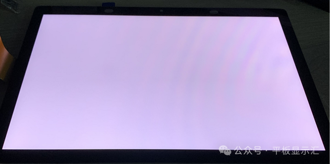 Illustration of Rainbow Pattern Phenomenon in TFT-LCD Display ModulesIt has been a while since we updated the【Practical Guide】, today we will write an article in the【Practical Guide】column, which you can quickly master and apply after reading, the kind that you can learn and use immediately.As industry professionals, when we confirm the subjective effects of TFT-LCD liquid crystal display modules, we often find some undesirable effects in all-white or grayscale images, such as“interference stripes, rainbow patterns, Newton’s rings” and other phenomena.These phenomena may not be clearly visible under normal observation angles and are often only discovered at specific angles, and the phenomena change with the change of observation angle.In the product development process, these undesirable phenomena can be prevented and some risks can be avoided during the early design, simulation, and material selection stages. After the samples are produced, through the adjustment of related materials and control of the manufacturing process, the severity of the undesirable effects can also be further reduced.When discussing the“rainbow pattern”phenomenon in TFT-LCD liquid crystal display modules, most readers may be familiar with it, especially those in product development and quality positions. However, when it comes to the mechanism of rainbow pattern generation and improvement strategies, many may not be clear.Today’s article will mainly focus on the rainbow pattern phenomenon and definition, the mechanism of rainbow pattern generation, and improvement strategies for rainbow patterns, helping readers gain a deeper understanding of rainbow patterns.At the same time, when encountering rainbow pattern issues at work, you can refer to the improvement strategies discussed in this article to help you solve them more quickly.01 Definition and Phenomenon of Rainbow PatternsRainbow patterns, also known as Color Mura, strictly speaking, there are two types of rainbow patterns we currently observe: “reflective rainbow patterns” and“transmissive rainbow patterns.”In TFT-LCD liquid crystal display modules, many optical films use PET as the substrate, such as diffusion films, brightness enhancement films, and ITO films of touch panels. When the light emitted by LEDs passes through these optical films, refraction and reflection occur within the optical films.Generally, rainbow patterns produced using PET substrates and reflective polarizers (i.e., APF brightness enhancement films) are basically classified as “reflective rainbow patterns,” which is Reflected Substrate Color Mura, abbreviated as RSCM.
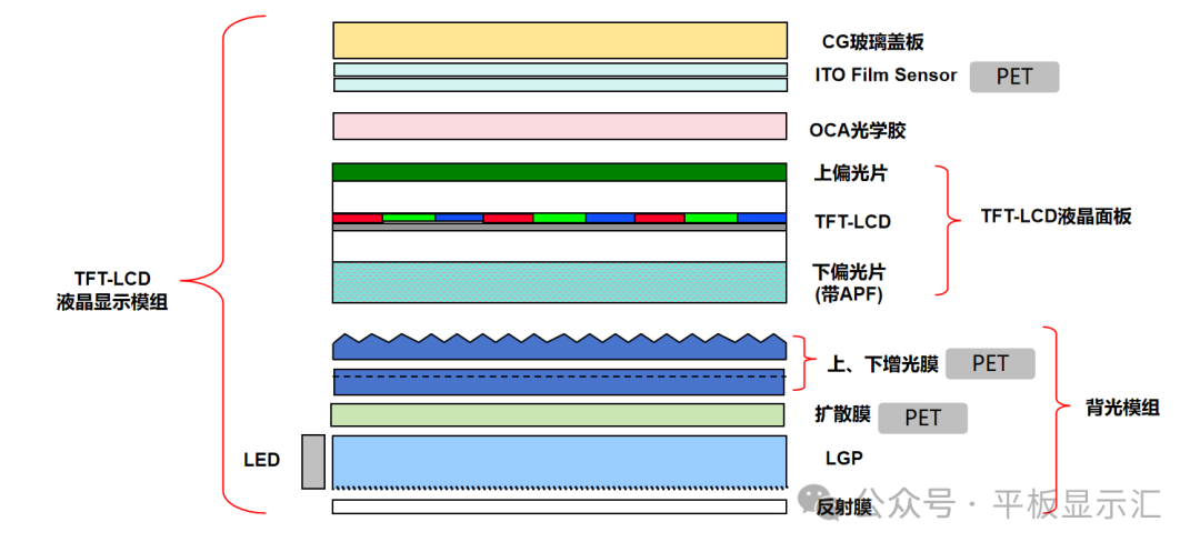 Material Stacking Diagram of TFT-LCD Liquid Crystal Display ModulesRainbow patterns are visual defects in TFT-LCD liquid crystal display modules caused by light interference resulting from the refraction and reflection of various optical materials, presenting as localized or overall colored stripes resembling a rainbow on an all-white screen; the colors of the stripes typically alternate or mix red, green, and blue interference colors, resembling a rainbow.The undesirable phenomenon of rainbow patterns usually has several key characteristics:①Rainbow-like morphology:The rainbow pattern phenomenon presents alternating interference colors of red, green, and blue (similar to the colors of soap bubbles or oil films), usually without a fixed shape, which may be stripe-like, blotchy, or mesh-like.②Visible at specific angles:Rainbow patterns can only be seen at specific observation angles, and the phenomenon may completely disappear or worsen with changes in observation angle.
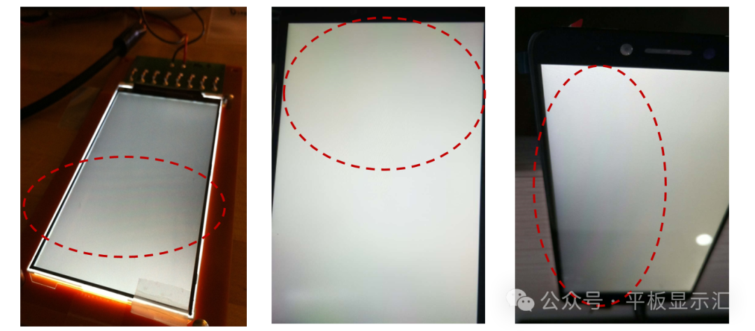 Illustration of Rainbow Pattern Defects
02 Mechanism of Rainbow Pattern Generation
Many optical films used in TFT-LCD liquid crystal display modules are based on PET, and there are several key characteristics of PET substrates that need to be briefly explained before discussing the mechanism of rainbow pattern generation to help readers better understand the mechanism.
①Anisotropy of PET
Anisotropy refers to the property of materials exhibiting different physical and optical properties in different directions, such as mechanical strength, thermal expansion coefficient, and optical characteristics.
For PET substrates, we know that the PET substrate used for optical films is produced through a biaxial stretching process. After stretching and cooling, the molecular chains are orderly and oriented along the stretching direction, and this arrangement leads to different physical and optical properties in different directions.Therefore, optical films made from PET substrates exhibit anisotropy.
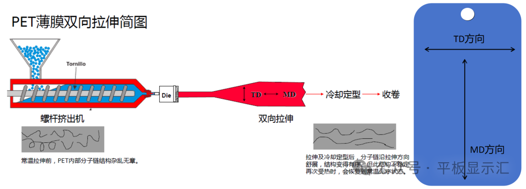
PET Substrate Biaxial Stretching Diagram
②Birefringence of PET
Birefringence is a manifestation of the anisotropy of PET substrates, primarily optical anisotropy.
When a beam of light enters a birefringent material like PET, it splits into two beams of linearly polarized light with perpendicular polarization directions, namely: extraordinary light (also called e-light) parallel to the optical axis and ordinary light (also called o-light) perpendicular to the optical axis, these two beams propagate at different speeds and paths.
The refractive indices of e-light and o-light in the material are different, i.e.,ne≠no, resulting in a phase difference (also called optical path difference) between the two beams, which may lead to interference.
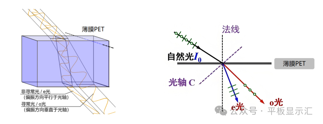
PET Birefringence Light Path Diagram
Based on the above explanation of the anisotropy and birefringence of PET films, we can summarize:PET film anisotropy is formed by the oriented arrangement of molecular chains after stretching, and the anisotropy of PET is the fundamental condition for birefringence, while birefringence directly leads to the accumulation of optical path differences, resulting in the occurrence of rainbow patterns.
With a clear understanding of the anisotropy and birefringence of PET films, the mechanism of interference pattern generation in TFT-LCD liquid crystal display modules becomes clear. In summary, the mechanism of rainbow pattern generation is:
1)Films made from PET substrates, such as diffusion films and upper and lower brightness enhancement films, cause birefringence due to the ordered arrangement of molecular chains from the stretching process.
2)When the light emitted by LEDs passes through diffusion films and upper and lower brightness enhancement films, birefringence causes light in different directions to have different propagation speeds and paths. When these light beams encounter multiple reflected and refracted light from other layers, such as polarizers, LCD display panels, OCA, and TP ITO films, optical path differences occur.
3)Due to the accumulation of optical path differences, interference effects are likely to occur, ultimately leading to the generation of rainbow patterns.
03 Improvement Strategies for Rainbow Patterns
In TFT-LCD liquid crystal display modules, there are many improvement strategies for rainbow patterns. Based on the mechanism of rainbow pattern generation, the improvement strategies can be broadly divided into four aspects:
①Reduce the use of birefringent PET materials
In TFT-LCD liquid crystal display modules, the materials that use PET substrates mainly include diffusion films, upper brightness enhancement films, lower brightness enhancement films, and ITO films on touch panels. In medium and small-sized display modules, diffusion films, upper brightness enhancement films, and lower brightness enhancement films are essential.
By reducing the use of PET substrate materials, birefringence can be minimized, thereby avoiding the occurrence of rainbow patterns from the source. Therefore, for touch methods, the In-cell solution can be used to replace the external solutions, such as GFF and GF.
If an external solution must be used, it is recommended to prioritize the GF solution, as the GFF solution has a gap between the two layers of ITO films, which increases the risk of light refraction in the gap, further raising the risk of rainbow patterns.
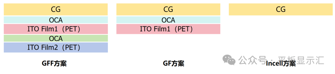
Illustration of Different Touch Solution Structures
②Change the light transmission path and re-match the optical path difference
In practical operations, there are two common methods to change the light transmission path and re-match the optical path difference, and these two methods have little impact on product performance.
1)Adjust the cutting angles of the upper and lower brightness enhancement films.While the prism angles of the upper and lower brightness enhancement films remain fixed, adjusting their cutting angles can change the angle between the cutting direction and the light incident direction and the LCD display panel, altering the refraction paths and reflection counts of light as it passes through each layer of film, thus re-matching the optical path difference and improving the rainbow pattern phenomenon.
2)Use brightness enhancement films with different stretching roll positions.The stretching degree of PET during the stretching process varies at different roll positions, leading to some differences in the arrangement of molecular chains, which results in differences in birefringence directions, ultimately affecting the severity of rainbow patterns on the surface.
Different stretching roll positions of brightness enhancement films can be verified by placing them in TFT-LCD liquid crystal display modules to observe the severity of rainbow patterns and select the best option.
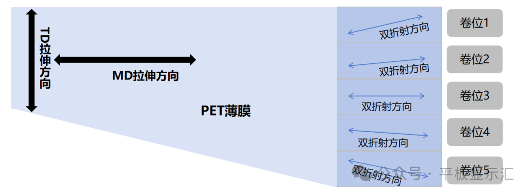
Illustration of Differences in Birefringence at Different PET Stretching Positions
③Increase material haze to disrupt light interference and reduce rainbow pattern visibility
Increasing material haze can be divided into two modules: increasing the haze of the backlight system and increasing the haze of the lower polarizer.Of course, increasing material haze will sacrifice some brightness, so a comprehensive consideration is needed.
1)Increase the haze of the backlight system.There are many ways to increase the haze of the backlight system, such as increasing the haze of the back coating of the upper brightness enhancement film, using high-haze lower diffusion films, and adding upper diffusion films in the backlight source (not using upper diffusion films in small-sized products).
2)Increase the haze of the lower polarizer.The method to increase the haze of the lower polarizer usually involves AG treatment (anti-glare) on the surface of the TAC layer of the polarizer, giving it a certain haze, such as 25% haze, and selecting sandpaper for the lower polarizer.
Increasing the haze of materials can cause incident light to undergo multiple random scatterings, with the phases of light from different scattering paths randomly distributed, disrupting light interference, thereby improving the rainbow pattern. At the same time, increasing material haze can also enhance shielding performance, reducing the visibility of rainbow patterns.
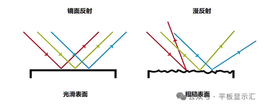
Illustration of Light Reflection on Smooth and Rough Surfaces
④Reduce the use of reflective lower polarizers
Reflective lower polarizers are what we commonly refer to as lower brightness enhancement films. The principle of brightness enhancement for these films is that they have multi-layer reflective polarized light characteristics, where P light can penetrate the core optical film layer of APF, while S light is reflected back, and the reflected S light is converted back to P light after passing through the core optical film layer, achieving multiple reflections and conversions of light, thus enhancing brightness.
For the mechanism of brightness enhancement of reflective polarizers, you can refer to my previous article:【Technical Insights】Understanding DBEF and APF Structures and Brightness Enhancement Principles
Due to the multiple reflections of light in reflective lower polarizers, the risk of optical path differences and light interference increases, which also raises the risk of rainbow patterns. Therefore, in cases where the brightness of TFT-LCD liquid crystal display modules is sufficient, it is advisable to avoid using reflective lower polarizers as much as possible.
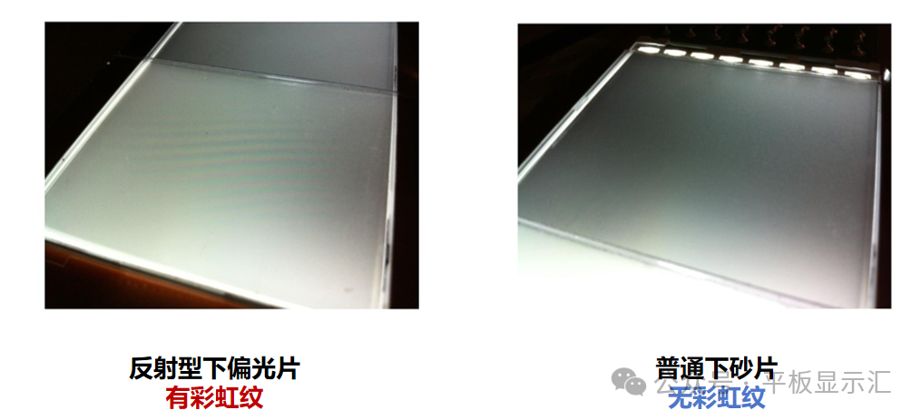
Comparison of Rainbow Patterns in Reflective Lower Polarizers and Ordinary Lower Polarizers
To reduce the risk of rainbow patterns, when using lower polarizers, it is preferable to choose ordinary lower sandpaper first, followed by ordinary lower polarizers, and to be cautious with reflective lower polarizers (APF brightness enhancement films).
 Source: Flat Panel Display Weekly