1. Introduction
Synchronization Rectifier:
The Power Management Integrated Circuit (PMIC) is an integrated circuit primarily used for managing and controlling electrical energy within electronic device systems, including but not limited to the following:
-
Voltage Conversion: Converts the power supply voltage to the appropriate voltage levels required by various parts of the electronic device, including Boost, Buck, and Buck-Boost conversion.
-
Current Control: Controls and limits the current flowing to various parts of the electronic device to protect components from overcurrent damage.
-
Power Rail Management: Manages multiple power rails to provide stable energy control for different parts. A power rail refers to the lines on a circuit board that transmit power.
-
Power Monitoring: Provides over-voltage, under-voltage, over-current, over-temperature, and short circuit protection to prevent damage to electronic devices.
-
Energy Conversion and Efficiency Optimization: Reduces energy loss and improves energy utilization efficiency through efficient power conversion technologies.
-
Remote Control and Monitoring: Allows remote control and monitoring of power status through communication interfaces (e.g., I2C, SPI, PMBus, etc.).
-
Fault Diagnosis: Provides fault detection and reporting functions to help diagnose and locate power-related issues.
-
Timing Control: Ensures that the power-up and power-down of the power supply occur in the correct sequence in complex electronic systems to avoid startup errors or hardware damage.
-
Integration: Integrates multiple power management functions into a single chip to reduce the number of external components, save space, and lower costs.
-
Programmable and Configurable: Allows power management parameters to be configured via software to meet different application needs.
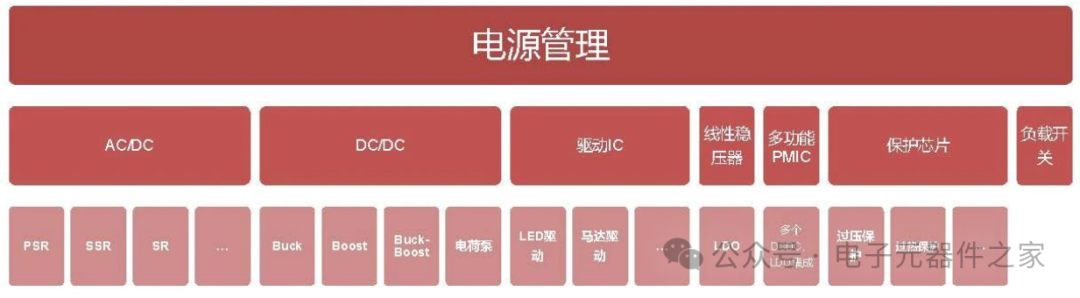
2. Classification
Power management chips can be classified into AC/DC (alternating current to direct current), DC/DC (direct current to direct current), driver I, protection chips, LDO, load switches, PMIC, etc.
Common power supplies are mainly divided into automotive and communication series, and general industrial and consumer series. The former typically uses voltages of 48V, 36V, 24V, etc., while the latter generally uses power supply voltages below 24V.
Different application fields have different rules, for example, PCs commonly use 12V, 5V, 3.3V, analog circuit power supplies commonly use 5V, 15V, and digital circuits commonly use 3.3V, 2.5V, etc. Nowadays, FPGAs and DSPs also use voltages below 2V, such as 1.8V, 1.5V, 1.2V, etc.
3. Voltage Monitoring
ADCMP361 is a comparator with a built-in reference voltage, bipolar output, and ±0.275% accuracy. Due to the built-in 400mV high-precision reference voltage source in ADCMP361, it can accurately monitor very low voltages, such as a 0.9V voltage rail. Each voltage rail uses independent circuits. A resistive voltage divider proportionally reduces the voltage rail and sets an undervoltage trip point for each power supply. All outputs are connected together to generate a general power good signal.
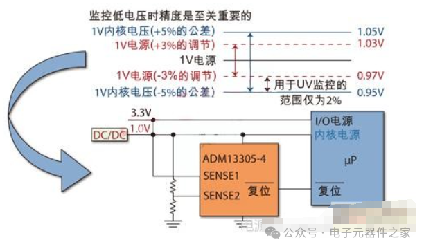
In this example, the actual voltage range of a 1V regulated power supply is 0.97V to 1.03V. The acceptable core voltage for the microprocessor is 1V (±5%), which means 0.95V to 1.05V. Therefore, the undervoltage monitoring range is 2%. The adjustable inputs of ADM13305, ADM13307, and ADM1184 have an accuracy of up to ±0.8% across the entire temperature range, and the accuracy of the resistive voltage divider is ±0.1%, which keeps the undervoltage level monitoring accuracy within 2%.
4. Timing Control
When monitoring multiple voltage rails, more than just simple voltage monitoring ICs are needed. For example, consider a common power sequencing control requirement: FPGA (Field Programmable Gate Array) manufacturers specify that the 5V I/O (Input/Output) voltage must be applied before the 3.3V core voltage and must be maintained for at least 20ms to avoid damage to the device during power-up.
Power Sequencing Methods
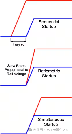
There are generally three types of multi-rail sequencing.
The most common method is sequential sequencing, where one power rail is turned on first, then delayed, and then the next power rail is turned on. The purpose of setting the delay is to ensure that the first power rail reaches regulation before the second power rail starts.
The second sequencing technique is ratio sequencing. In this technique, the power rails start simultaneously and reach their respective rated voltages simultaneously. This requires the rise time of the power rail to be proportional to the power rail voltage to achieve regulation simultaneously.
Some devices may not withstand the instantaneous voltage difference that occurs before reaching regulation. This may cause the device to draw higher current from one power supply during this period.
The third method is simultaneous startup, which minimizes instantaneous voltage differences and reduces the scale and period of these stresses. A common way to implement this method is to power on simultaneously, i.e., the voltage rails rise together at the same rate, with the higher voltage rail (usually the I/O voltage rail) continuing to rise after the lower voltage rail or core voltage rail reaches its final value.
Regardless of the technique used, the voltage must rise monotonically. Otherwise, the device may fail to initialize correctly due to an unexpected drop in voltage during startup.
Additionally, soft-start can be used to limit inrush current during startup. This practice can limit current during startup, allowing gradual charging of the power rail capacitors.
The power shutdown sequence is usually specified to be the opposite of the startup sequence.
The choice of which startup or shutdown technique to use should depend on the specifications of the device.
Discrete devices implement basic timing control
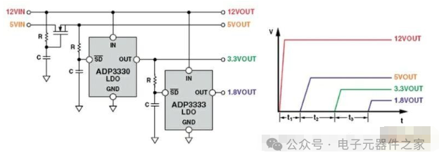
Here, logic levels rather than comparators are used. The 12V and 5V power rails are generated by other circuits. To ensure that the system operates correctly, a time delay must be introduced. This is achieved by slowly raising the gate voltage of the N-channel FET in series with the 5V power supply using an RC (resistor-capacitor) circuit. The selected RC values ensure that there is sufficient delay before the FET reaches the threshold voltage and turns on. The 3.3V and 1.8V power rails are generated by linear regulators ADP120 and ADP130. The power-up times of these voltages are also controlled using RC for timing. Since the RC can drive the EN (enable) pin of each LDO, there is no need to use a series FET. The selected RC values must ensure there is sufficient delay before the voltage at the EN pin rises to its threshold (t2, t3).
This simple, low-cost power sequencing control method occupies very little circuit board area, making it suitable for various applications. This method is suitable for systems where cost is the primary consideration, timing requirements are simple, and precision in timing control circuits is not particularly important. However, many situations require higher precision than RC delay circuits. Additionally, this simple solution does not allow for structured fault handling (for example, a failure in a 5V power supply will ultimately affect other power rails).
Using ICs for Timing Control
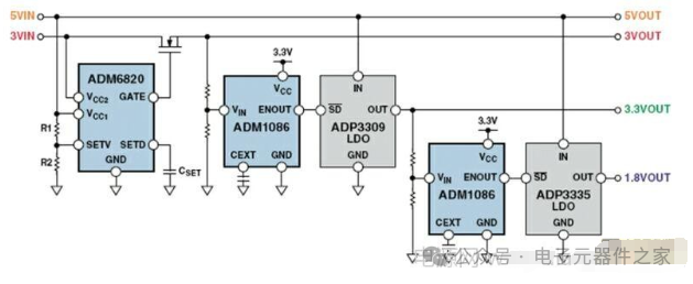
Using the power sequencing controller ADM6820 and ADM1086 to accurately and reliably control the timing of power rails in the system. The internal comparator detects when the voltage rail exceeds the precise set level, and after a programmable power-on delay, it generates an output to allow linear regulators ADP120 and ADP130 to operate according to the desired timing. The threshold is set by the resistor ratio, and the delay is set by the capacitor.
One-click triple support for the author 👉 Share ↓ Like ↓ View ↓