Overview of PMIC for Raspberry Pi 4B – MaxLinear MxL7704
I am using the Raspberry Pi 4B, and its PMIC is located at the position shown in the image below. The PMIC chip has the inscription “MXL7704-P4” on it.
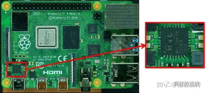
This chip is from MaxLinear, and you can find the information about MxL7704 on their official website. According to the description, MxL7704 is a power management chip designed for low-power FPGAs, DSPs, and MCUs, featuring 5 outputs: 4 are synchronous buck regulators and 1 is a low-dropout regulator (LDO). Additionally, it has an I2C interface for dynamic voltage adjustment, power-up/power-down sequence control, and PGOOD status monitoring.
It looks quite complicated, so today I will introduce the MxL7704. Below is the homepage of its Datasheet:
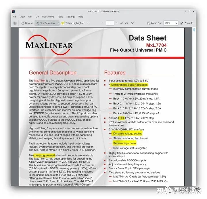
I have highlighted the key points discussed in this article in yellow on the homepage of the Datasheet as follows:
-
What are synchronous buck regulators and low-dropout regulators (LDO)?
-
What is dynamic voltage scaling?
-
What is sequencing control?
-
Why is pre-programming necessary?
Then I will answer two questions:
-
Is the Raspberry Pi PMIC prone to failure?
-
If it fails, can it just be replaced with another one?
What are Synchronous Buck Regulators and Low-Dropout Regulators (LDO)?
Both are types of voltage regulators, and both are buck converters, meaning the output voltage must be lower than the input voltage.
A synchronous buck regulator is a DC-DC switching power supply device that operates based on the principle that inductor current cannot change instantaneously. It controls the charge and discharge of the inductor with switch transistors. In the first stage, switch S1 is closed while switch S2 is open, allowing the input voltage Vin to charge inductor L1, resulting in an output voltage Vo that is less than Vin. In the second stage, switch S1 is open while switch S2 is closed, and inductor L1 discharges as an energy source (the current direction remains unchanged), maintaining that the voltage across inductor L1 is less than Vin, thus keeping the output voltage Vo also less than Vin. These stages alternate, and with capacitor filtering, stable buck voltage can be achieved at the output.
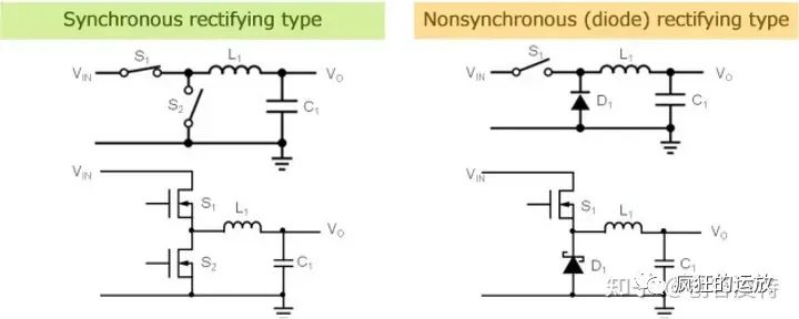
The term “synchronous” in synchronous buck regulator refers to the synchronized operation of switches S1 and S2. In contrast, in an asynchronous configuration, switch S2 is replaced by diode D1. This configuration can also achieve buck conversion but is considered to have lower energy conversion efficiency.
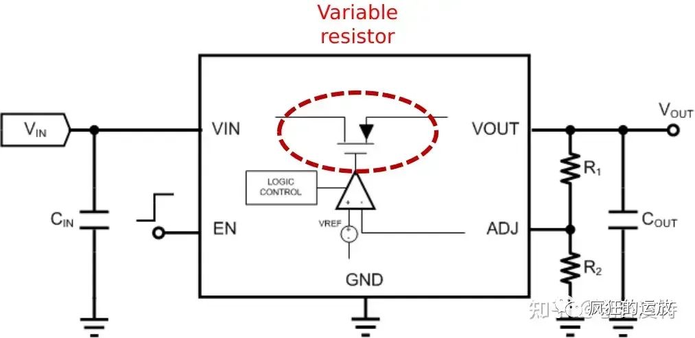
A low-dropout linear regulator (LDO) operates by controlling the conduction of a transistor, functioning as a variable resistor, and using the ratio of the resistances of the variable resistor and load to divide the voltage. This division can dynamically adjust based on the output load, maintaining the output voltage at a specific level.
When comparing synchronous buck regulators with low-dropout linear regulators, the following characteristics are typically noted:
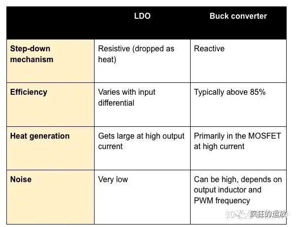
This should be easy to understand because LDOs rely on variable resistors for voltage division, which consumes energy and results in inefficient energy usage, hence lower efficiency. For this reason, LDOs are not recommended for high current outputs. As you can see on the datasheet of MxL7704 in Figure 2, the LDO output is only 100mA, while the synchronous buck regulator can output between 1.5 to 4A. Therefore, the latter is more suitable for powering SoCs.
What is Dynamic Voltage Scaling (DVS)?
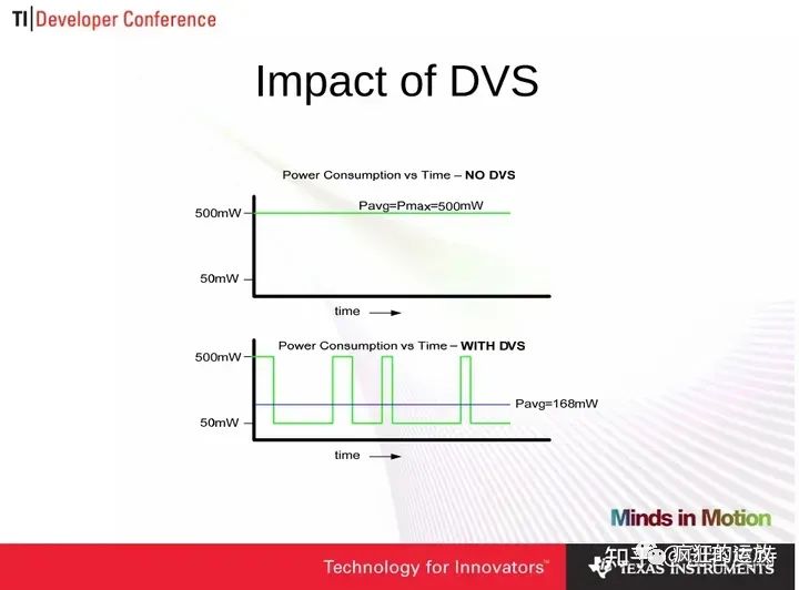
Dynamic voltage scaling (DVS) optimizes the power supply voltage under different operating states. It is generally believed that reducing the CPU frequency can linearly decrease power consumption, and when combined with DVS, it can exponentially reduce device power consumption to the maximum extent. The following image is a diagram illustrating the concept of DVS presented by TI:
What is Sequencing Control?
For FPGA devices, the power-up sequence typically starts with core voltage and ends with I/O voltage. Similarly, there is a specific sequence requirement for power-down. For ARM MCU devices, it is somewhat different, usually starting with I/O power-up followed by core power-up.
The MxL7704 is a PMIC specifically designed to power FPGAs, DSPs, and MCUs, with two models provided by the manufacturer, as shown in the lower right part of Figure 2:
-
MxL7704-A IO rails up first, core last (1.2V)
-
MxL7704-X for Xilinx© ZU2 and ZU3 MPSoCs
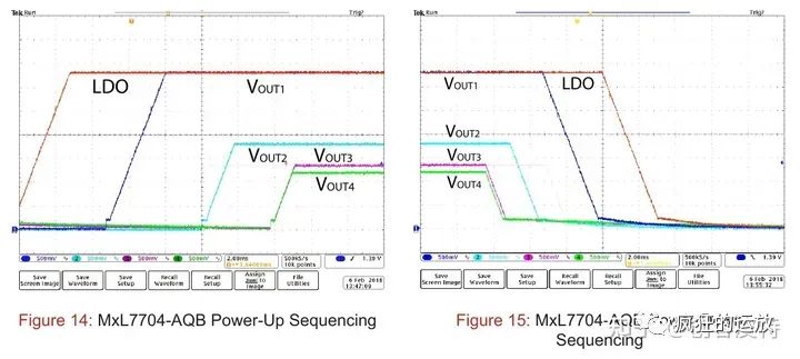
MxL7704-A is for ARM MCU use, while MxL7704-X is for FPGA use. Taking MxL7704-A as an example, we can see its power-up and power-down sequence control from the Datasheet:
Why is Pre-Programming Necessary?
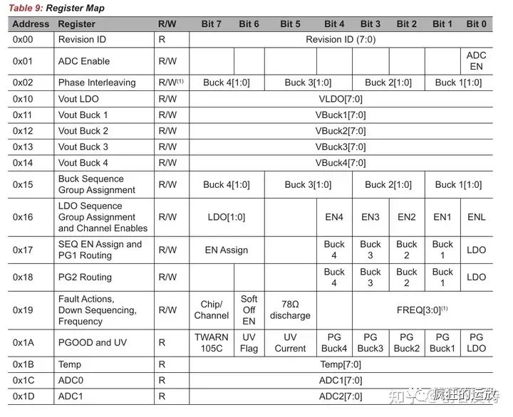
The MxL7704 has 0x1D registers that can be configured via I2C, involving configurations such as the output voltage levels, sequence control, status monitoring, and fault handling. The register topology is shown below:
Please note that the MxL7704 on our Raspberry Pi 4B is marked as MXL7704-P4, which is neither MxL7704-A nor MxL7704-X. This suggests that it may be a chip specially supplied by MaxLinear for Raspberry Pi, and the specifics of this “special supply” should reflect in the register configuration data.
Is the Raspberry Pi PMIC Prone to Failure?
Some users from abroad have mentioned that since the Raspberry Pi 3B, the PMIC has been the MxL7704, with a common issue being that if you accidentally short-circuit the 5V and 3.3V, you may damage the PMIC, rendering the Raspberry Pi unusable.
So you need to be particularly careful when handling the 5V and 3.3V voltage rails of the Raspberry Pi as they are prone to failure.
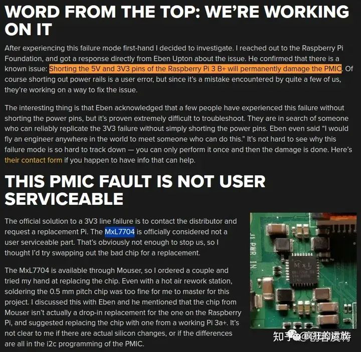
If the Raspberry Pi PMIC Fails, Can It Just Be Replaced?
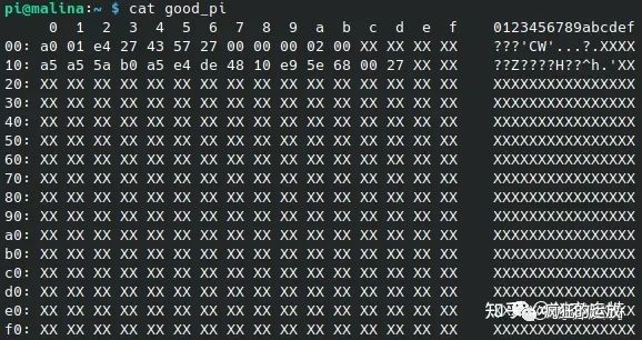
According to references from hackaday [Link 3] and Raspberry Pi forums [Link 4], some users reported that after their PMIC failed, they bought a non-MXL7704-P4 chip and soldered it on, but it didn’t work. They needed to perform I2C pre-programming. This resourceful user happened to have two Raspberry Pi 4Bs and successfully read the register data from one MXL7704 and wrote it into another MXL7704.
Here we share the extracted register data for future reference…
Reference Links
[1] Home – MaxLinear
[2] https://hackaday.com/2019/06/12/shorting-pins-on-a-raspberry-pi-is-a-bad-idea-pmic-failures-under-investigation/
[3] https://hackaday.com/2023/03/24/dead-raspberry-pi-boards-pmics-and-new-hope/
[4] RaspberryPi 4 MXL7704-R4 PMIC replacement and repair
(End of article)
This column is an interesting and useful software and hardware column designed for makers. If you find it helpful, please click the “Like” button in the lower right corner and follow this public account. This is my greatest motivation~