1. Purpose
|
Standardize the PCB pad design process for products, specifying the relevant parameters of the PCB pad design process, ensuring that the PCB design meets the technical specifications for manufacturability, testability, safety regulations, EMC, EMI, etc., and building the process, technology, quality, and cost advantages of the product during the design process. |
2. Scope of Application
This specification applies to the PCB process design of household electronic products, used in but not limited to PCB design, PCB mass production process review, single board process review, and other activities.
In case of any conflict between the contents of previous relevant standards and specifications and the provisions of this specification, this specification shall prevail.
3. References/Standards
TS—S0902010001 <<Safety Design Specifications for Information Technology Equipment PCB>>
TS—SOE0199001 <<Forced Air Cooling Design Specifications for Electronic Equipment>>
TS—SOE0199002 <<Natural Cooling Design Specifications for Electronic Equipment>>
IEC60194 <<Terms and Definitions for Printed Board Design, Manufacture, and Assembly>>
IPC—A—600F <<Acceptability of Printed Boards>>
IEC60950
4. Specification Content
4.1 Definition of Pads
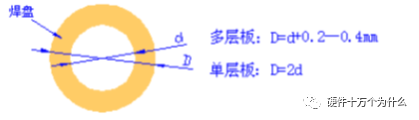
The outer shape of through-hole pads is usually circular, square, or elliptical. Specific size definitions are detailed below, with terminology definitions as shown in the figure.
1) Hole diameter size:
If the actual pin is circular: Hole diameter (diameter) = actual pin diameter + 0.20 to 0.30mm (8.0 to 12.0MIL);
If the actual pin is square or rectangular: Hole diameter (diameter) = size of the diagonal of the actual pin + 0.10 to 0.20mm (4.0 to 8.0MIL).
2) Pad size:
Conventional pad size = hole diameter (diameter) + 0.50mm (20.0 MIL).
4.2 Related Specifications for Pads
4.2.1 The minimum distance from the edge of all pads should not be less than 0.25mm, and the maximum diameter of the entire pad should not exceed three times the component hole diameter.
Generally, through-hole components use circular pads, with the pad diameter being more than 1.8 times the insertion hole diameter; single-sided board pad diameter should not be less than 2mm; double-sided board pad size should ideally have a ratio of 2.5 to the through-hole diameter. For components that can be used with automatic insertion machines, the double-sided board pads should be the standard hole diameter +0.5 to +0.6mm.
4.2.2 Ensure that the distance between the edges of two pads is greater than 0.4mm, and for a row of pads perpendicular to the wave peak direction, the distance between the edges of two pads should be greater than 0.5mm (at this time, this row of pads can be considered as a line group or socket, and too close a distance can easily cause bridging).
In cases of dense wiring, it is recommended to use oval and elongated connection pads. The diameter or minimum width of single-sided board pads should be 1.6mm or ensure a single-sided pad ring of 0.3, and for double-sided pads, 0.2; oversized pads can lead to unnecessary solder bridging. In cases of high-density wiring, it is recommended to use circular and elongated pads. The pad diameter is generally 1.4mm or even smaller.
4.2.3 Pads with a hole diameter greater than 1.2mm or a pad diameter greater than 3.0mm should be designed as star-shaped or flower-shaped pads.
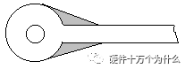
For plug-in components, to avoid copper foil breakage during soldering, the connection points on single-sided boards should be fully covered with copper foil; for double-sided boards, the minimum requirement should be a teardrop (see the attachment for the hole control section); as shown in the figure:
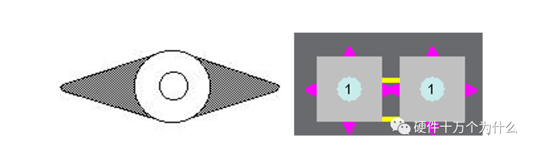
4.2.4 For all force-bearing components or heavy components, the width of the copper film covering the pad lead within 2mm should be increased as much as possible, and there should be no empty pad designs to ensure that the pad can hold enough solder, and the socket will not easily lift the copper foil under external force. For large components (e.g., transformers, electrolytic capacitors with a diameter greater than 15.0mm, high-current sockets, etc.), increase the copper foil and solder area as shown in the figure; the shaded area must be at least equal to the pad area. Alternatively, design as flower-shaped or star-shaped pads.
4.2.5 All magnetic components must have a solid base, and the use of non-base magnetic components is prohibited.
4.4.6.18 For the layout requirements of through-hole reflow soldering components:
a. For PCBs with a non-transport edge size greater than 300mm, heavier components should not be placed in the center of the PCB to reduce the impact of the weight of plug-in components on PCB deformation during soldering, as well as the impact on components already placed on the board during the insertion process.
b. For ease of insertion, components are recommended to be placed close to the insertion operation side.
c. For longer components (e.g., memory module sockets), the length direction is recommended to be consistent with the transport direction. Components with multiple pins in the same line, connectors, DIP packaged components, and T220 packaged components should be laid out parallel to the wave soldering direction. Lighter components such as diodes and 1/4W resistors should be laid out perpendicular to the wave soldering direction. This can prevent floating phenomena during wave soldering due to one end being soldered first and solidifying.
5. Related Management Content
5.1 Component Pad Packaging Library
5.2 The processability of PCB pad design must comply with the above rules while allowing for specific variations based on actual design needs.
This article’s source cannot be verified; if the author sees this, please contact us for proper attribution.
【1】Interest-driven passion
【2】Should hardware engineers draw PCBs themselves?
【3】How long should PCB traces be??
【4】How wide should PCB traces be?
【5】Inner layers of PCB
【6】Through holes
【7】Can PCBs have sharp angles and right angles?
【8】Should dead copper be retained? (PCB islands)
【9】Can holes be drilled on pads??
【10】PCB materials,What does FR4 refer to?
【11】Solder mask,Why is green oil mostly green?
【12】Steel mesh
【13】Pre-layout
【14】Key points of PCB layout and routing
【15】Cross-segment routing
【16】Signal reflection
Dirty signals
Surface treatment processes such as gold plating, tin plating, etc.
Line spacing
Placement of capacitors
Crosstalk
PCB flying needle testing
Overview and simulation of FPC
Why does PCB deform and bend? How to solve it?
Understanding “characteristic impedance” in one article
PCB stacking design
High-speed circuit PCB reflow path
Power handling and plane segmentation in PCB design
Zigzag PCB routing—Tabbed routing
What is the dielectric loss angle of PCB?
How does copper foil roughness affect high-speed signals?
Why can’t crystal oscillators be placed at the edge of the PCB?
What is a high-speed signal?
What is a transmission line?
Pre-emphasis, de-emphasis, and equalization
How to utilize PCB heat dissipation
“Stub” in PCB design
Controversy: Should there be a GND protection line between traces?
PCB copper pouring
Rules to follow when designing PCBs
“Pseudo eight-layer” in PCB stacking design
In addition to strip lines and microstrip lines, there are also “co-planar waveguides”
Hard Ten has published books


“DCDC Power Supply” is in the publishing process, expected to be released in May, stay tuned.