Author | cxuan
Source | Java Builders
Assembly code is a low-level representation of a computer, which is a low-level language that can be understood literally, including data processing, memory management, reading and writing data on storage devices, and utilizing network communication, etc. The compiler generates machine code through a series of transformations that follow the programming language, the target machine’s instruction set, and the operating system.
Instruction Set
The instruction set refers to the commands that direct the computer’s operations, as programs are sequences of instructions arranged in a specific execution order. Since the execution control of the computer is managed by the CPU, the instruction set is a collection of commands used by the CPU to compute and control the computer. Each CPU specifies an instruction set that works in conjunction with its hardware circuitry at the time of production.
Instruction sets can be classified in various ways, but they are generally divided into two types: Reduced Instruction Set and Complex Instruction Set. The specific descriptions are as follows:
Reduced Instruction Set
The English term for reduced instruction is reduced instruction set computer, RISC, which originally means reduced instruction set computing. It is a design pattern for CPUs, where the CPU can be imagined as an assembly line factory that simplifies the number of instructions and addressing modes, making implementation easier, improving instruction parallel execution, and enhancing compiler efficiency.
Common RISC processors include: ARM, AVR, MIPS, PARISC, RISC-V, and SPARC.
So you can understand:
What this book is about.
It mainly introduces the hardware implementation and software design of the five components of the von Neumann architecture based on the MIPS architecture. More importantly, it introduces many parallel computing concepts, which are often overlooked or have limited content in most textbooks. This book will integrate parallel-related content with OpenMP, CUDA, and Hadoop/Spark, as this is the trend for future development.
And this book:
What this book is about.
This book discusses the RISC-V instruction set, as the differences in instruction sets also distinguish three versions. Three versions??? Well, there’s also this one:
This book discusses the ARM instruction set.
So generally, it is a very good choice to read this book concurrently while looking at CASPP.
RISC generally has the following characteristics:
- Unified instruction encoding.
- General-purpose registers, typically distinguishing between integer and floating-point.
- Simple addressing modes, with complex addressing modes replaced by simple instruction sequences.
- Support for very few niche types, such as RISC supporting byte string types.
Complex Instruction Set
The English term for complex instruction set is Complex Instruction Set Computing, abbreviated as CISC, which is a microprocessor instruction set architecture, also translated as complex instruction set.
Complex instruction sets include: System/360, VAX, x86, etc.
Complex instruction sets can be seen as modifications made on top of reduced instruction sets.
The characteristics of complex instruction sets are that they have many complex instructions, and the length of each instruction word is not equal, requiring the computer to interpret them, which incurs a performance cost.
Generally, methods to enhance CPU performance include:
- Increasing the size of registers
- Enhancing internal parallelism
- Increasing the size of caches
- Increasing core clock speed
- Adding other functionalities, such as I/O and timers
- Incorporating vector processors
- Hardware multithreading technology
The C compiler receives other operations and converts them into assembly language output, which is a machine-level code representation. We know that the execution process of a C language program is divided into the following steps:
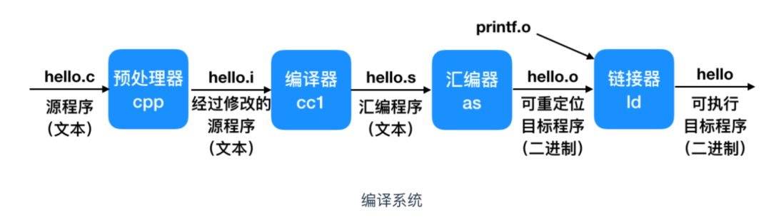
From now on, most of our discussions will be based on assembly code.
The high-level languages we encounter daily are the result of multiple layers of abstraction, so we usually do not come into contact with assembly language, nor do we program in assembly language. This is similar to not knowing the existence of the operating system, but every operation you perform, even double-clicking an icon, is related to the operating system.
High-level languages have a high level of abstraction, but after multiple layers of abstraction, the execution efficiency of high-level languages is certainly not as high as that of assembly language, nor is it as reliable.
However, high-level languages have the significant advantage of being able to run on different machines after compilation, while assembly language has different representations for different instruction sets. Moreover, high-level languages are easier to learn and understand, lowering the barrier to entry for computing, which leads to more competition (of course, this is a joke, please don’t take offense).
To put it simply, to understand the lower levels, one must understand assembly language. Otherwise, a synchronized low-level implementation can give you a headache. Moreover, floating around every day is not good; you will eventually have to land.
Understanding assembly code also helps us optimize program code, analyze hidden inefficiencies in the code, and once this optimization is successful, it will be a significant improvement, not just a minor change like modifying an if…else or using a new feature.
Machine-Level Code
Computer systems use various forms of abstraction to hide implementation details through a simple abstract model. For machine-level programs, two points are very important.
First, the format and behavior of machine-level programs are defined by the instruction set architecture (ISA). The ISA defines the process state, the format of instructions, and the effect of each instruction on the state. Most instruction set architectures include ISA to describe the behavior of processes as if they are executed sequentially, where one instruction finishes executing before the next one begins. The description of processor hardware is more complex; it can execute many instructions in parallel, but it employs safety measures to ensure that the overall behavior is consistent with the order specified by the ISA.
Second, the machine-level description of memory addresses is the virtual address, which provides a memory model to represent a large byte array.
The compiler plays a crucial role throughout the compilation process, converting C language into the basic instructions executed by the processor. Assembly code is very close to machine code, but compared to binary machine code, assembly code is more readable, so understanding assembly is the first step to understanding how machines work.
Some process states are visible to the machine, but C language programmers cannot see them, including:
Program Counter, which stores the address of the next instruction, represented as%ripin the x86-64 architecture.
When a program executes, the initial value of the PC is the address of the first instruction of the program. In sequential execution, the CPU first fetches an instruction from memory at the address indicated by the program counter, then analyzes and executes that instruction, while incrementing the value of the PC by 1 to point to the next instruction to be executed.
For example, here is a snippet of code performing addition:
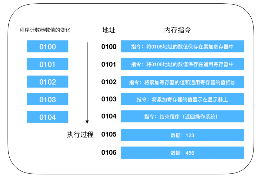
This is an operation for adding values. When the program starts, after being compiled and parsed, the operating system copies the program from the hard disk into memory. The example program adds 123 and 456 and outputs the result to the display. Since it is difficult to describe using machine language, this is the translated result. In reality, each instruction and data may be distributed across different addresses, but for convenience, the memory and data that make up an instruction are placed at one memory address.
- The integer
register filecontains 16 named locations for storing 64-bit values. These registers can store addresses and integer data. Some registers are used to track program status, while others are used to store temporary data, such as procedure parameters and local variables, as well as the return value of functions. Thisfileis unrelated to disk files; it is simply a high-speed storage unit within the CPU. There are dedicated registers and general-purpose registers for storing operands. Condition Code Registeris used to store status information about the most recently executed arithmetic or logical instructions. These are used to implement conditional changes in control or data flow, such as the conditions required for if and while statements. We have all learned high-level languages, and the control flow in high-level languages mainly consists of three types:sequential execution, conditional branching, and loop judgment. Sequential execution executes instructions in the order of their addresses. Conditional branching executes instructions at arbitrary addresses based on conditions. Loops repeatedly execute instructions at the same address.- Sequential execution is relatively simple; the value of the program counter is +1 for each executed instruction.
- Conditional and loop branches can cause the program counter to point to arbitrary addresses, allowing the program to return to the previous address to repeat the same instruction or jump to any instruction.
Next, let’s illustrate the execution process of a program using conditional branching (loops are similar).
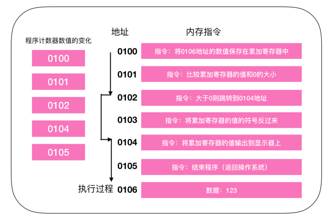
The initial process of the program is the same as the sequential flow; the CPU starts executing commands from address 0100. At addresses 0100 and 0101, it executes sequentially, incrementing the PC value by 1. When it reaches the instruction at address 0102, it checks if the value in register 0106 is greater than 0, jumps (jumps) to the instruction at address 0104, outputs the value to the display, and then ends the program, skipping the instruction at 0103. This is similar to the if() judgment in our programs; when the condition is not met, the instruction is skipped directly. Therefore, the execution process of the PC does not increment directly by 1 but points to the address of the next instruction.
- A set of
vector registersis used to store one or more integer or floating-point values, and vector registers operate on one-dimensional data.
Machine instructions only perform very simple operations, such as adding two numbers stored in registers, transferring data from memory to registers, or conditionally branching to a new instruction address. The compiler must generate sequences of such instructions to construct programs, such as evaluating arithmetic expressions, loops, or procedure calls and returns.
Understanding Assembly
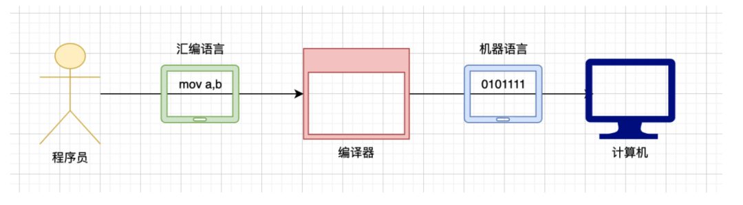
I believe everyone should know the background of the emergence of assembly language, which is that binary representation of data is too complex and cumbersome. To solve this problem, assembly language was created. The difference between assembly language and machine instructions lies in the representation method; assembly uses operands for representation, while machine instructions use binary. I have previously mentioned that machine code is assembly; you cannot say I am wrong, but it is not accurate.
However, assembly has a conversion relationship with binary code.
Assembly code needs to be compiled by an assembler to produce binary code, which is the object code, and then linked by a linker to run.
Assembly language is mainly divided into the following three categories:
- Assembly instructions: These are
mnemonicsfor machine code, which have corresponding machine codes. - Pseudoinstructions: These do not have corresponding machine codes and are executed by the compiler; the computer does not execute them.
- Other symbols, such as +, -, *, /, etc., recognized by the compiler, which do not have corresponding machine codes.
The core of assembly language is assembly instructions, and our discussion of assembly is based on assembly instructions.
Hardware and Concepts Related to Assembly
CPU
The CPU is the brain of the computer; it is also the core of the entire computer and the hardware that executes assembly language. The CPU contains registers, which are used to store instructions and data. The essence of assembly language is a series of calculations executed by the operands within the CPU.
Memory
Without memory, a computer is like a human without memory, endlessly repeating the same tasks. The instructions and data required by the CPU are provided by memory, and CPU instructions are provided by memory, which are then output to memory after a series of calculations.
Disk
The disk is also a storage device, and its main difference from memory is permanent storage. Programs need to be loaded into memory before they can run, and the programs provided to memory are stored on the disk.
Bus
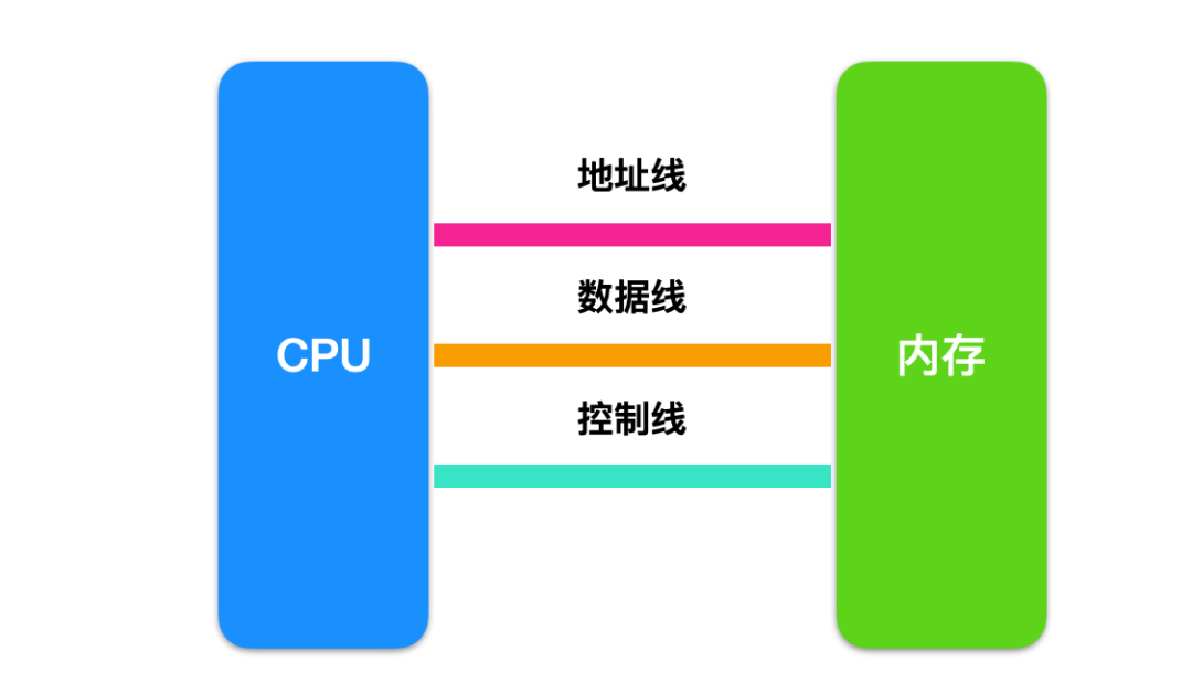
Generally, memory is divided into multiple storage units, which are used to store instructions and data, like houses, where storage units are the house numbers. The interaction between the CPU and memory occurs through the address bus, which is logically divided into three types:
- Address lines
- Data lines
- Control lines
The read and write operations between the CPU and memory mainly go through the following steps:
Read Operation Steps
- The CPU sends the location of the instruction to be read via the address line.
- The CPU sends a read instruction via the control line.
- The memory places the data on the data line and returns it to the CPU.
Write Operation Steps
- The CPU sends the location of the instruction to be written via the address line.
- The CPU sends a write instruction via the control line.
- The CPU writes the data into memory via the data line.
Now let’s take a closer look at these three types of buses:
Address Bus
From our previous discussion, we know that the CPU specifies the storage location through the address bus. The number of different pieces of information that can be transmitted on the address bus determines how many storage units the CPU can address.
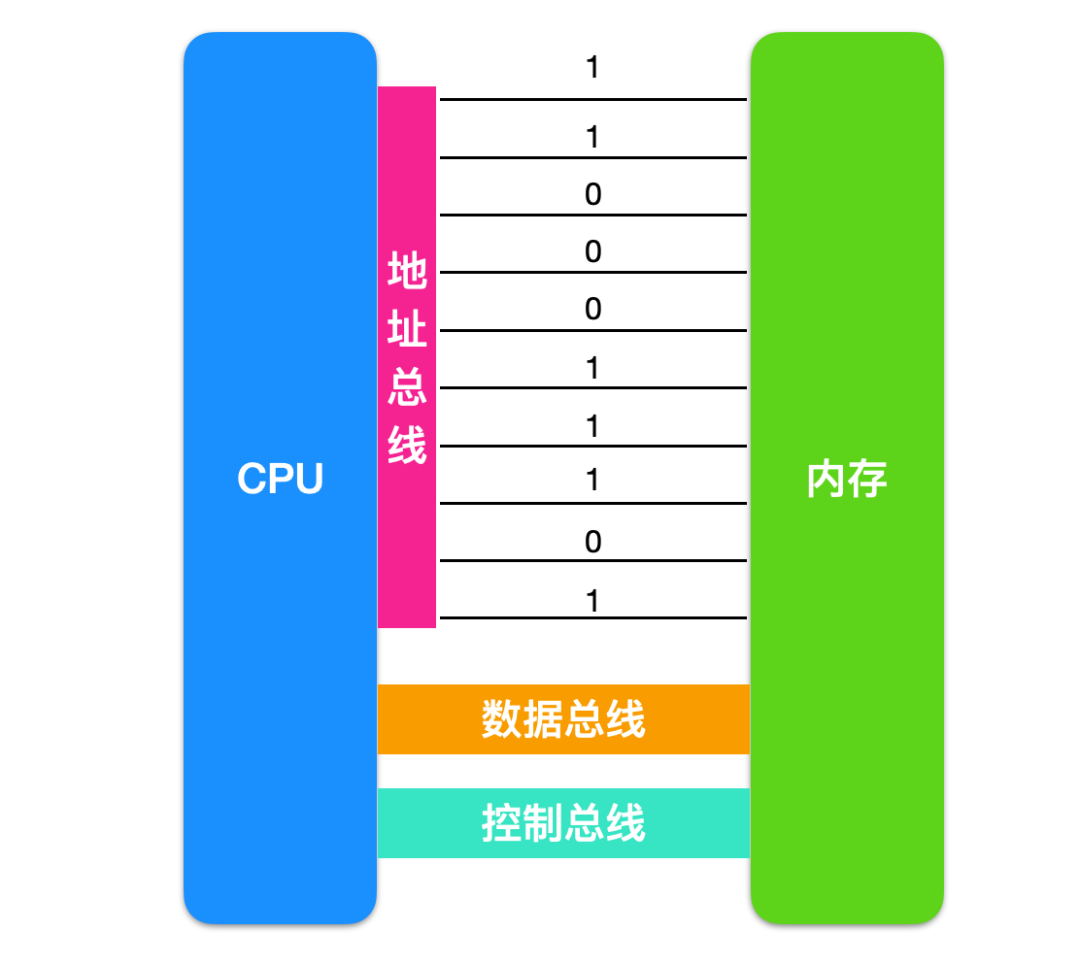
In the image, the information exchange between the CPU and memory occurs through 10 address lines, where each line can transmit data as 0 or 1. Therefore, the data transmitted between the CPU and memory at once is 2 to the power of ten.
Thus, if the CPU has N address lines, we can say that the width of this address bus is N. This way, the CPU can search for 2 to the power of N memory units.
Data Bus
The data transfer between the CPU and memory or other components is accomplished by the data bus. The width of the data bus determines the speed of data transfer between the CPU and the outside world. Eight data lines can transmit one 8-bit binary data (i.e., one byte) at a time. Sixteen data lines can transmit two bytes at once, and thirty-two data lines can transmit four bytes at once…
Control Bus
The control of the CPU over other components is accomplished through the control bus. The number of control lines indicates how many types of control the CPU provides to external devices. Therefore, the width of the control bus determines the CPU’s control capability over external components.
A Memory Read Process
Memory Structure
The memory IC is a complete structure that also contains power, address signals, data signals, control signals, and IC pins for addressing to read and write data. Below is a schematic diagram of a virtual IC pin:
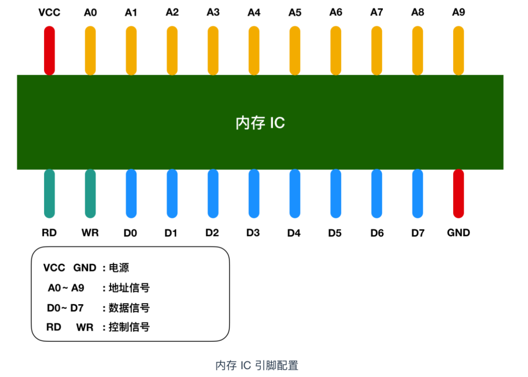
In the image, VCC and GND represent power, A0 – A9 are address signal pins, and D0 – D7 represent data signals. RD and WR are control signals, which I have distinguished by different colors. After connecting the power to VCC and GND, signals of 0 and 1 can be transmitted to other pins. In most cases, +5V represents 1, and 0V represents 0.
We know that memory is used to store data, so how much data can this memory IC store? D0 – D7 represent data signals, meaning that 8 bits = 1 byte of data can be input and output at once. A0 – A9 are address signals, totaling ten, indicating that we can specify from 00000 00000 to 11111 11111, which is 2 to the power of 10 = 1024 addresses. Each address will store 1 byte of data, so we can conclude that the capacity of the memory IC is 1 KB.
If we are using 512 MB of memory, that is equivalent to 512000 (512 * 1000) memory ICs. Of course, it is unlikely for a computer to have so many memory ICs; however, typically, a memory IC will have more pins, allowing it to store more data.
Memory Read Process
Now let’s detail the memory read process.

To describe this process in detail, suppose we want to write 1 byte of data into the memory IC; the process is as follows:
- First, connect +5V power to VCC and 0V power to GND, use
A0 - A9to specify the storage location of the data, then input the value of the data to theD0 - D7data signals, and set the value ofWR (write)to 1. After completing these operations, data can be written to the memory IC. - To read data, simply specify the storage location of the data using the A0 – A9 address signals, and set the value of RD to 1.
- In the image, RD and WR are also known as control signals. When both WR and RD are 0, writing and reading operations cannot be performed.
Conclusion
This article mainly discussed instruction sets, the classification of instruction sets, the hardware related to assembly, and the functions of buses, followed by an understanding of the CPU and memory interaction process through a memory read process.