A microcontroller (Single-Chip Microcomputer) is an integrated circuit chip that uses ultra-large scale integration technology to integrate a central processing unit (CPU), random access memory (RAM), read-only memory (ROM), multiple I/O ports, an interrupt system, timers/counters, and other functions (which may also include display driver circuits, pulse width modulation circuits, analog multiplexers, A/D converters, etc.) onto a single silicon chip, forming a compact and complete microcomputer system that is widely used in industrial control.
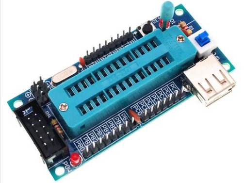
Image of a microcontroller
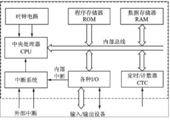
Block diagram of a microcontroller
The arithmetic logic unit (ALU) consists of several parts, including the arithmetic logic unit, accumulator, and registers. The ALU’s role is to perform arithmetic or logical operations on the incoming data, which comes from two 8-bit data sources: the accumulator and the data register. The ALU can perform addition, subtraction, logical AND, logical OR, and comparisons, ultimately storing the result in the accumulator.
The ALU has two functions:
(1) Execute various arithmetic operations.
(2) Execute various logical operations and perform logical tests, such as zero value tests or comparisons between two values.
All operations executed by the ALU are directed by control signals from the controller, and each arithmetic operation produces one result, while each logical operation results in one decision.
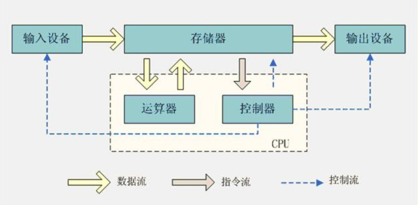
The controller consists of the program counter, instruction register, instruction decoder, timing generator, and operation controller. It serves as the “decision-making body” that issues commands, coordinating and controlling the operations of the entire microcomputer system. Its main functions include:
(1) Fetching an instruction from memory and indicating the next instruction.
(2) Decoding and testing the instruction, generating corresponding control signals to facilitate the execution of the specified actions.
(3) Directing and controlling the flow of data between the CPU, memory, and input/output devices.
Within the microprocessor, the ALU, counters, registers, and control sections are interconnected via an internal bus, and they connect to external memory and input/output interface circuits through an external bus. The external bus, also known as the system bus, is divided into data bus (DB), address bus (AB), and control bus (CB). Input/output interface circuits facilitate connections to various peripheral devices.
(1) Accumulator A
The accumulator A is an 8-bit binary register with a special purpose, specifically designed to store operands or results of operations. Before the CPU performs a certain operation, one of the two operands is usually placed in accumulator A, and after the operation is completed, the result can be found in accumulator A.
(2) Data Register DR
The data register (Data Register, DR), also known as the data buffer register, primarily serves as a transit point for information transfer between the CPU and main memory or peripheral devices, compensating for speed differences in operations between the CPU and main memory or peripherals. The data register temporarily holds an instruction or a data word read from main memory; conversely, when an instruction or data word is written to main memory, it is also temporarily stored in the data register.
(3) Instruction Register IR and Instruction Decoder ID
Instructions consist of operation codes and operands.
The instruction register is used to hold the instruction currently being executed. When executing an instruction, it is first fetched from memory into the data register, and then transferred to the instruction register. When the system executes a given instruction, the operation code must be decoded to determine the required operation, which is the responsibility of the instruction decoder. The output of the operation code field in the instruction register serves as the input for the instruction decoder.
(4) Program Counter PC
(5) Address Register AR
The address register (Address Register, AR) is used to store the address of the memory unit currently accessed by the CPU. Due to speed differences between main memory and the CPU, the address register must temporarily hold the main memory address information until the memory access operation is completed. When the CPU exchanges information with main memory, whether writing data/instructions to main memory or reading data/instructions from main memory, the address register and data register are used. If we unify the addressing of peripheral devices with main memory units, then when the CPU exchanges information with peripheral devices, we also need to use the address register and data register.
Clearly, when the CPU writes data to memory, reads data from memory, and fetches instructions from memory, the address register and data register are utilized. Similarly, if the addresses of peripheral devices are treated as memory address units, then when the CPU exchanges information with peripheral devices, the address register and data register are also required.
Due to the frequent portability of smart electronic devices, there are very high energy consumption requirements for these devices, which often leads to the design of energy-saving control modules to enhance the standby time of smart electronic devices. The application of microcontroller technology in energy-saving control mainly falls into the following aspects: First, when smart electronic devices are in an outdoor state, they are mostly in a light load mode, requiring energy-saving control to further reduce power consumption while ensuring basic functionality. Microcontrollers can infer that the current device is in a lower load state by collecting data from the smart electronic devices, allowing for a reduction in voltage and current output to achieve energy savings; Second, microcontrollers can control the rhythm of energy consumption. For example, in the Xiaomi Mi Band, it collects data on heart rate, sleep, and step count, which is stored locally and reported at a frequency of once per minute. When information is not being reported, the device remains in a low-energy state, and while reporting information, there will be some consumption related to network transmission. Microcontrollers can control the rhythm of energy consumption, keeping the band in a low-energy state for most of the time, allowing for standby times of over seventy-two hours.

(1) Long lifespan; products developed with microcontrollers possess good stability and a long service life, capable of stable operation for 10 to 20 years.
(2) High speed; by improving the internal timing without increasing the clock frequency, the computation speed of microcontrollers has been further enhanced.
(3) High reliability and low noise technology.
(4) Mask and OTP; OTP belongs to one-time programmable microcontrollers. In the past, the production of mask microcontrollers was considered a sign of maturity for microcontroller products, as masks have corresponding production cycles. With the decreasing prices of OTP microcontroller models, manufacturing products through OTP has gradually become a trend in recent years. Compared to the mask method, OTP has advantages such as lower risk and shorter production cycles.


Editor | Chen Yiyu
Source Material | Chen Yiyu Baidu
Material Compilation | Chen Yiyu
Reviewed by | Shi Rui
Final Review | Du Wei