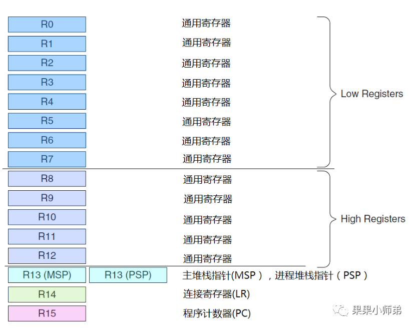
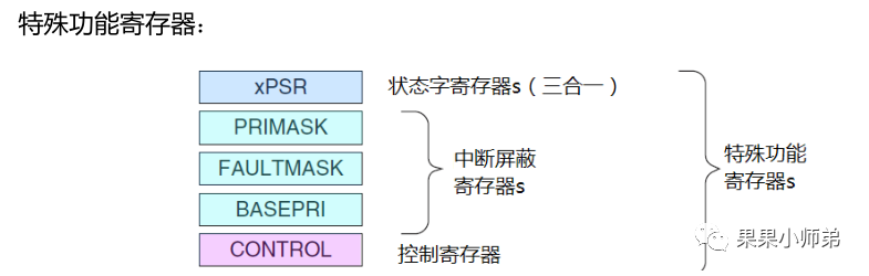
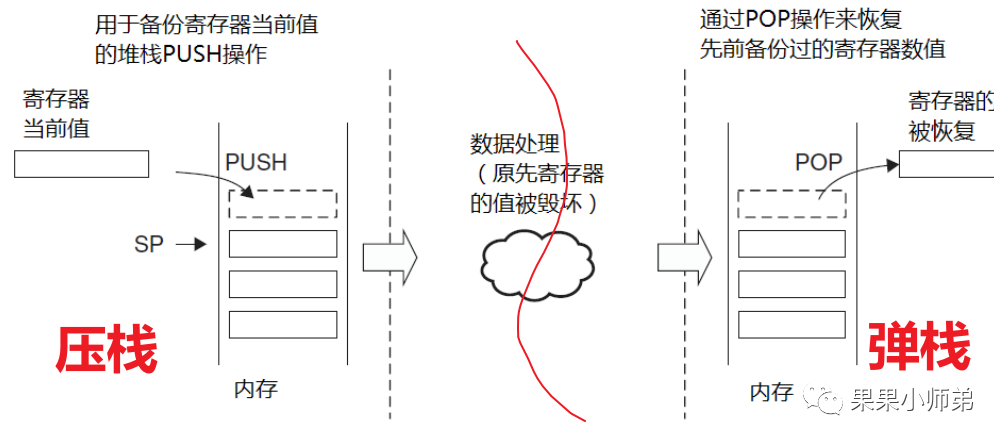
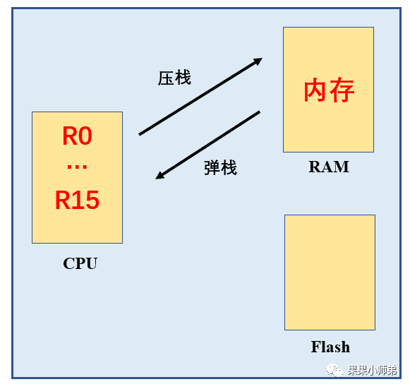
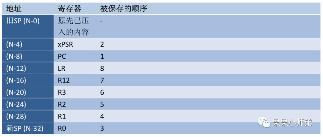
Abstract:We encounter many operating systems, such as Windows, Android, iOS, and Linux, which are all types of operating systems. Microcontrollers also have their own operating systems, known as real-time operating systems. So what are the differences between these real-time operating systems and the systems we use?The operating systems we commonly use are actually non-real-time operating systems. Why are they considered non-real-time? Because their kernel actually uses a time-slicing scheduling method for tasks. For example, if there are three tasks: Task A, Task B, and Task C, the time-slicing scheduling mechanism will let Task A run for a while, then switch to Task B, and then switch to Task C, continuously rotating among them.A simple model of round-robin scheduling between two tasksWhat is the downside of this? If Task C in an autonomous vehicle is responsible for detecting and avoiding obstacles, and if Task C cannot be executed in a timely manner, the autonomous vehicle may crash into an obstacle, which is very dangerous. Hence, we have the emergence of real-time operating systems that support preemptive scheduling mechanisms, meaning we can increase the priority of Task C. This ensures that when Task C is ready, it runs first, guaranteeing its real-time performance. The most fundamental function of an operating system is to implement task scheduling.Next, let’s understand FreeRTOS, the task scheduling of real-time operating systems. Before understanding real-time operating systems, we need to first understand the kernel, using the ARM Cortex-M3 kernel as a template. First, let’s understand the CPU registers, here is the table of CM3’s CPU registers. CM3 has general-purpose registers R0-R15 and some special function registers. R0-R12 are the most “general-purpose”, but the vast majority of 16-bit instructions can only use R0-R7 (low group registers), while 32-bit Thumb-2 instructions can access all general-purpose registers. Special function registers have predefined functions and must be accessed via specific instructions.Register set of Cortex-M3As can be seen, the front part consists of general-purpose registers. They are divided into low registers (accessible by all instructions) and high registers (only accessible by a few 16-bit Thumb instructions). Why are they divided this way? In fact, in earlier versions of the ARM core, ARM instructions and Thumb instructions could access different registers, hence the distinction between low and high registers. The subsequent R13, R14, and R15 are the stack pointer, link register, and program counter register, respectively.In addition, CM3 has some special registers.Have you ever thought about how the CPU enters an interrupt, which essentially interrupts the previous task? After executing the interrupt, how does the CPU return to the original task? And how does it ensure that the original task is not lost?Before entering the interrupt, that is, in the left half, we first save the values of the CPU registers into memory, also known as pushing to the stack. Then we run the interrupt service function, during which the CPU registers will be modified. But that doesn’t matter, because when the interrupt ends and returns to the original task, the previous values of the CPU registers will be retrieved from memory, known as popping from the stack. This mechanism ensures that the data of the original process is not lost.Next, let’s understand the stack pushing order of CM3?The order of stacking and the content in the stack after stacking is shown in the third columnThe above figure shows the hardware stack pushing order when Cortex-M3 enters an interrupt. When it enters an interrupt, the hardware automatically pushes these several registers onto the stack: the PC pointer, the xPSR special register, general-purpose registers R0 to R3, general-purpose register R12, and the LR link register (which saves the return address of the function) will be pushed onto the stack in the order indicated in the third column below.After successfully pushing onto the stack, when the interrupt execution is complete and returns to the original process, the contents of the stack will be popped back to the CPU registers in the reverse order of the pushing order. This means that LR is popped first, and then the others are popped in order, as the stack is last in, first out.Earlier, we learned that the CPU has R0-R15 and several special registers. When the interrupt function arrives, the above registers are automatically pushed onto the stack by hardware, but there are also some that are pushed onto the stack by software. How should we understand this?For example:When the program executes
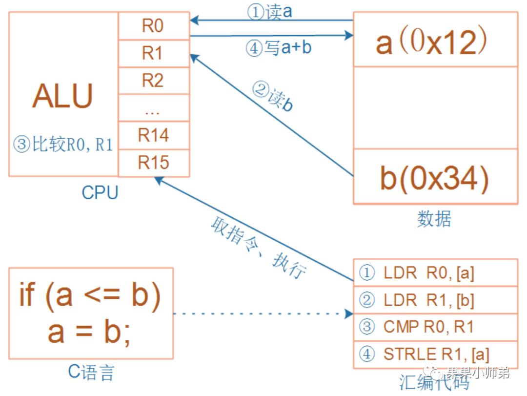
if(a<=b)
 a=b;
and is suddenly interrupted. Any program will eventually be translated into machine code, and the above C code can be converted into the assembly instructions on the right.For these four instructions, they may be interrupted by an exception at any time. How can we ensure that after the exception is handled, the interrupted program can still run correctly?These four instructions involve the R0 and R1 registers. When the program is interrupted and resumes running, R0 and R1 must remain unchanged. After executing the third instruction, the comparison result is stored in the program status register PSR, which must remain unchanged during interruption and resumption. These four instructions read the memory of a and b, and the memory must remain unchanged during interruption and resumption. Maintaining the memory unchanged is easy to achieve as long as the program does not go out of bounds. Therefore, the key is that R0, R1, and the program status register must remain unchanged (of course, there are more than these registers):
Before handling the exception, save these registers onto the stack, which is called saving the context, or stack pushing.
After handling the exception, restore these registers from the stack, which is called restoring the context, or stack popping.
Let’s take another example:
void A()
{
    B();
}
For instance, if function A calls function B, function A should know: R0-R3 are used to pass parameters to function B; function B can modify R0-R3 as it pleases; function A should not expect function B to save R0-R3; saving R0-R3 is the responsibility of function A; the same logic applies to LR and PSR, their preservation is also the responsibility of function A. This is done with the help of hardware.For function B: if I use any of R4-R11, I will save it at the function entry and restore it before returning, popping from the stack to the CPU registers; ensuring that R4-R11 remains unchanged for function A before and after the call to function B.Assuming function B is the exception/interrupt handler, and function B itself guarantees that R4-R11 remain unchanged, then during context saving, the hardware only needs to save R0-R3, R12, LR, PSR, and PC, which are the 8 registers.Next, let’s understand the two special interrupt mechanisms in CM3. When CM3 begins to respond to an interrupt, three hidden flows surge within it:
Stack pushing: Push the values of 8 registers onto the stack.
Vector fetching: Find the corresponding service program entry address from the vector table.
Select stack pointer MSP/PSP: Update the stack pointer SP, update the link register LR, and update the program counter PC.
The first is called tail-chaining interrupt
We know that entering an interrupt requires executing stack pushing, and exiting an interrupt requires executing stack popping. When two interrupts occur, like executing the first interrupt and then executing the second interrupt, the CM3 processor core will not execute stack popping and pushing again. This means it saves the time of stack popping and pushing, essentially allowing the second interrupt to “bite off the tail” of the first interrupt. This is why it is called a tail-chaining interrupt.
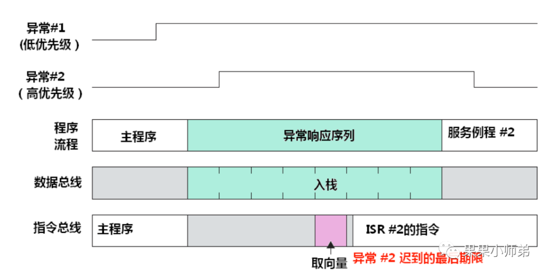
The second interrupt mechanism is called late arrival interrupt
Late arrival interrupt means that when a high-priority task arrives, if the previous low-priority task’s vector fetching has not yet completed (the previous low-priority task has not yet found the corresponding service program entry address from the vector table), then this stack pushing is for the high-priority task. This means that even if the high-priority interrupt arrives late, it can still use the stack pushed by the low-priority interrupt.
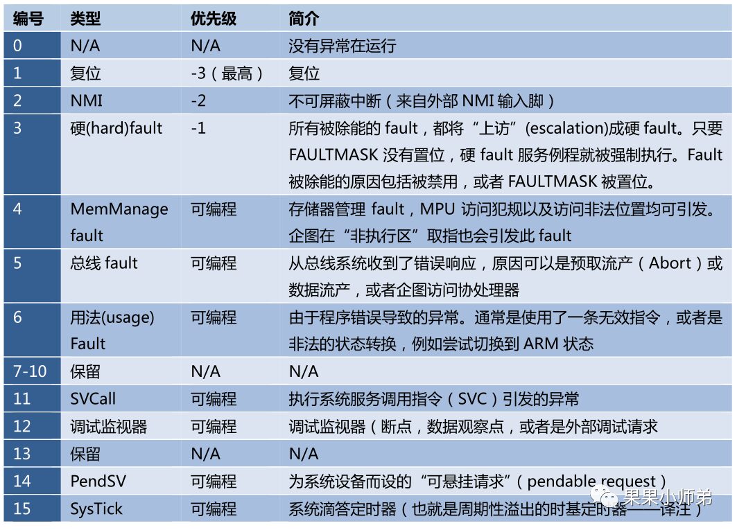
Interrupt table of the CM3 processor core
In real-time operating systems, the three interrupts frequently used are PendSV, Systick, and SVC.In FreeRTOS, the Systick interrupt is used to provide the clock cycles for the real-time operating system. The PendSV is a pendable interrupt used to switch processes. The SVC in FreeRTOS is only used once, which is during the startup of the first process.
__asm void vPortSVCHandler( void )
{
/* *INDENT-OFF* */
    PRESERVE8

    ldr r3, = pxCurrentTCB   // Get the current task control block
    ldr r1, [ r3 ] // Use pxCurrentTCBConst to get the pxCurrentTCB address
    ldr r0, [ r1 ] // The first item in pxCurrentTCB is the stack top task
    ldmia r0 !, { r4 - r11 } // Manually push R4-R11 and R14 registers onto the stack
    msr psp, r0    // Restore the task stack pointer
    isb
    mov r0, # 0
    msr basepri, r0 // Enable all interrupts
    orr r14, # 0xd
    bx r14
/* *INDENT-ON* */
}
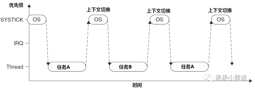
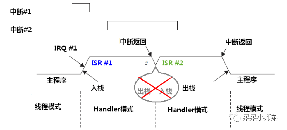
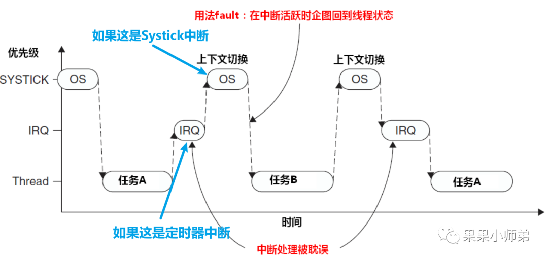
System exception listSome may ask, why not switch tasks directly in the Systick interrupt? Instead, why switch tasks in the PendSV? Let’s look at it:Context switching issues during IRQIf the Systick interrupt arrives while an interrupt is being executed (the IRQ is executing), it will be interrupted, and Systick will execute the context switch. At this point, switching to task b will have to wait until the next context switch to return to the original IRQ execution. Thus, the interrupt can only be completed later, which can significantly delay the interrupt execution. Therefore, this approach is inconvenient and prone to error.They came up with a solution: during the Systick, check if there is an interrupt being executed. If there is, do not switch; if not, switch. However, this can also lead to issues. If the interrupt function’s duration is similar to that of the Systick, for example, if it is a timer interrupt and both the Systick and the timer interrupt have a period of 1 millisecond, they may often face the situation of both arriving simultaneously. This can cause delays in process switching, hence this approach is not ideal either.
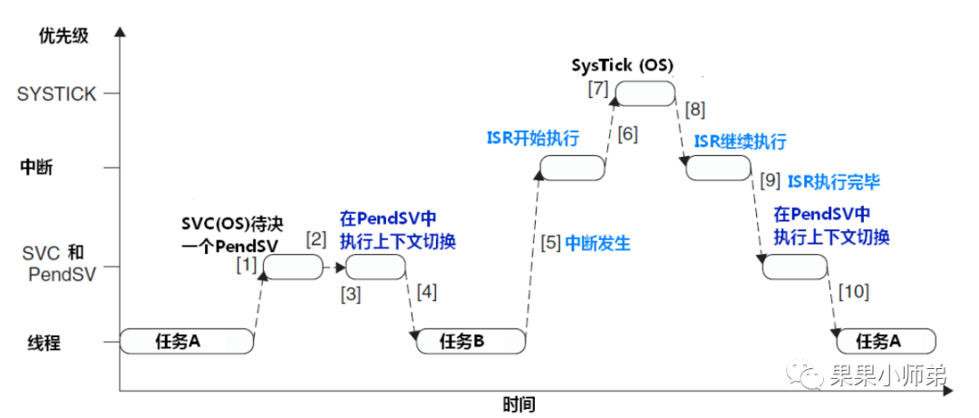
Thus, the PendSV pendable interrupt was created
Using PendSV to control context switchingWhat are the benefits of this interrupt? We can see that in the Systick, it only sets the PendSV interrupt bit to pending, meaning it does not perform frequent switching operations. Instead, it waits until all interrupts have been executed, and then performs the context switch in PendSV. This ensures timely switching of tasks and timely execution of interrupts. The PendSV exception will automatically delay the request for context switching until other ISRs have completed processing. To implement this mechanism, PendSV needs to be programmed as the lowest priority exception. If the OS detects that an IRQ is active and is preempted by Systick, it will pend a PendSV exception to delay the context switch execution.So how does context switching occur in PendSV? This is done using assembly language.
__asm void xPortPendSVHandler( void )
{
    extern uxCriticalNesting;
    extern pxCurrentTCB;
    extern vTaskSwitchContext;

    PRESERVE8

    mrs r0, psp// Save the current process stack pointer in R0 register
    isb

    ldr r3, =pxCurrentTCB // Get the current task control block
    ldr r2, [ r3 ] // Save the task control block address in R2 register

    stmdb r0 !, { r4 - r11 } // Manually push R4-R11 and R14 registers onto the stack
    str r0, [ r2 ] // Write the current stack top address into the control block

    stmdb sp !, { r3, r14 }
    mov r0, #configMAX_SYSCALL_INTERRUPT_PRIORITY// Write the immediate number represented by this macro into R0 register, which is the highest priority interrupt to be masked by the user
    msr basepri, r0 // Write the value of R0 register into the special register basepriority, which allows fine control of interrupts; it can unmask interrupts higher than this priority and mask those lower than this priority
    dsb
    isb
    bl vTaskSwitchContext
    mov r0, #0
    msr basepri, r0 // Cancel interrupt masking
    ldmia sp !, { r3, r14 } // Restore the current stack pointer from R3 register; at this point, R3 register holds the value just fetched from the next task control block

    ldr r1, [ r3 ]
    ldr r0, [ r1 ] // Save the new task's stack top into R0 register
    ldmia r0 !, { r4 - r11 } // Manually pop R4-R11 and R14 registers from the stack
    msr psp, r0
    isb
    bx r14  // Return from exception; after return, the hardware will automatically restore the remaining registers and use the process stack pointer.
    nop
/* *INDENT-ON* */
}
We have just learned the most basic function of task switching in the FreeRTOS real-time operating system. However, to create a complete real-time operating system, many other components are required, such as lists and list items, task notifications, low power mode task control blocks, memory management, idle tasks, semaphores, software timers, event flag groups, etc.References:
"FreeRTOS Source Code Detailed Explanation and Application Development"
"Authoritative Guide to ARM Cortex-M3"
Let’s take a look at how interrupts are implemented in the program
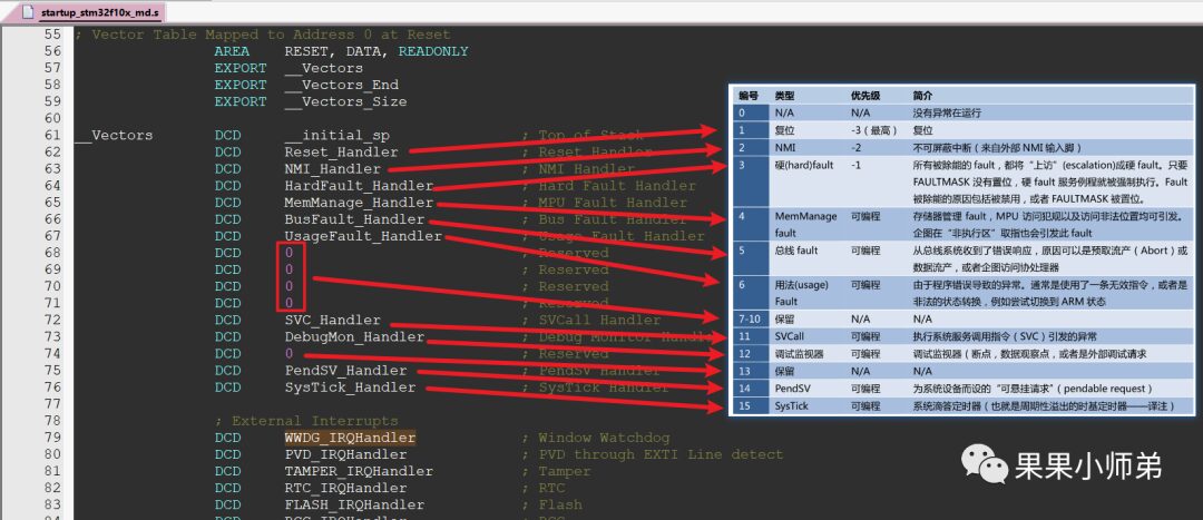
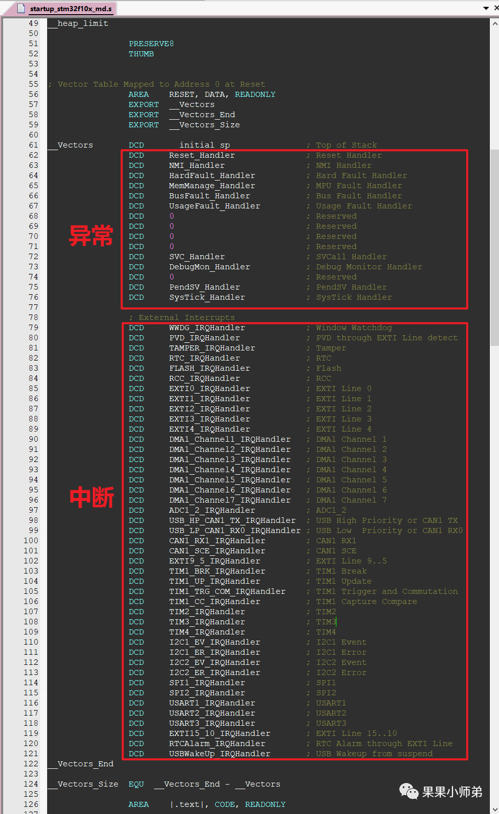
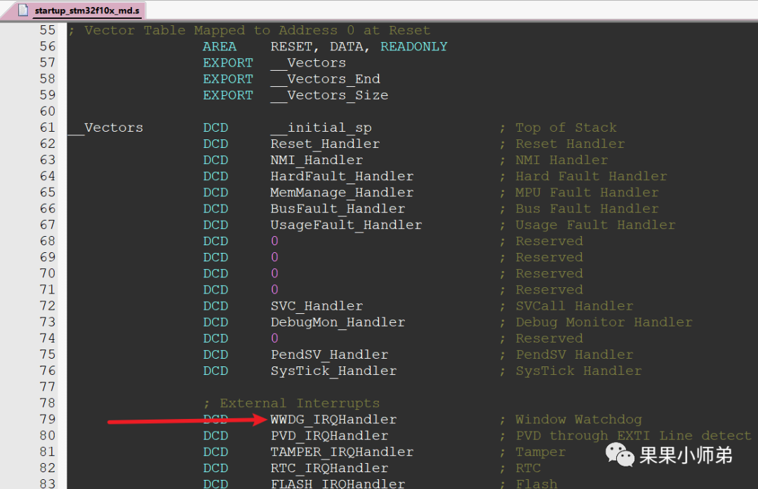
The following table comes from the “Authoritative Guide to ARM Cortex-M3”In Cortex-M3, there are 15 exception interrupts, corresponding to the following in STM32In the startup file, there are not only exceptions but also interrupts; in fact, interrupts are also a type of exception. When we talk about interrupts, we are often referring to signals sent by certain devices, such as GPIO modules: sending signals to the CPU, for example, when the I2C controller finishes sending data, it sends a signal to the CPU, or when UART receives data, it also generates an interrupt. Note: Interrupts are a type of exception. Besides interrupts, what other exceptions are there? Reset: also an exception, Various errors: also exceptions.When our board is reset, the CPU executes the Reset_Handler function in the interrupt vector table.When our board experiences a watchdog interrupt, the CPU executes the WWDG_IRQHandler function in the interrupt vector table.You must have such a question: How does the CPU know which function to jump to in the interrupt vector table?This is determined by the hardware because, at this moment, the software has not yet begun execution; the hardware determines which exception or interrupt has occurred, and when recovering, it is triggered by software, and the hardware restores it.
/**
  * @brief  This function handles NMI exception.
  * @param  None
  * @retval None
  */
void NMI_Handler(void)
{
}

/**
  * @brief  This function handles Hard Fault exception.
  * @param  None
  * @retval None
  */
void HardFault_Handler(void)
{
  /* Go to infinite loop when Hard Fault exception occurs */
  while (1)
  {
  }
}

/**
  * @brief  This function handles Memory Manage exception.
  * @param  None
  * @retval None
  */
void MemManage_Handler(void)
{
  /* Go to infinite loop when Memory Manage exception occurs */
  while (1)
  {
  }
}

/**
  * @brief  This function handles Bus Fault exception.
  * @param  None
  * @retval None
  */
void BusFault_Handler(void)
{
  /* Go to infinite loop when Bus Fault exception occurs */
  while (1)
  {
  }
}

/**
  * @brief  This function handles Usage Fault exception.
  * @param  None
  * @retval None
  */
void UsageFault_Handler(void)
{
  /* Go to infinite loop when Usage Fault exception occurs */
  while (1)
  {
  }
}

/**
  * @brief  This function handles SVCall exception.
  * @param  None
  * @retval None
  */
void SVC_Handler(void)
{
}

/**
  * @brief  This function handles Debug Monitor exception.
  * @param  None
  * @retval None
  */
void DebugMon_Handler(void)
{
}

/**
  * @brief  This function handles PendSVC exception.
  * @param  None
  * @retval None
  */
void PendSV_Handler(void)
{
}

/**
  * @brief  This function handles SysTick Handler.
  * @param  None
  * @retval None
  */
void SysTick_Handler(void)
{
}
Alright, now you know the interrupt process of the MCU and the basic principles of RTOS, right?
Author: Zhiguo Xin, Source: Guoguo Xiaoshidi
Disclaimer: This article is reproduced with permission from the “Guoguo Xiaoshidi” public account. Reproductionis for learning reference only and does not represent the views of this account. This account is not responsible for any infringement of its content, text, or images.
END♥Click 👇 the business card to follow me♥Previous Recommendations1. Adjustment of Onboard Antenna for Wireless Modules2. PCB Design of DCDC Power Module3. Basics of Microcontrollers: Do You Understand LED Driving?