The microcontroller’s CPU, while processing an event A, receives a request to quickly handle another event B (interrupt occurs); the CPU temporarily interrupts its current work to process event B (interrupt response and interrupt service); upon completing event B, the CPU returns to the original point of event A that was interrupted to continue processing event A (interrupt return). This process is called an interrupt.
For example,
when you are doing laundry and suddenly your phone rings (interrupt occurs), you temporarily stop doing laundry to answer the call (interrupt response and interrupt service), and once you finish the call, you return to continue doing laundry (interrupt return). This process is an interrupt.
Microcontroller interrupts are divided into two main categories: internal interrupts and external interrupts. External interrupts are generated by devices outside the microcontroller, and after the interrupt is generated, it is transmitted to the microcontroller through external pins. The simplest way to transmit this interrupt signal is to specify the conditions under which an external interrupt is generated on the microcontroller’s pins. Typically, the microcontroller has one or more I/O ports that can be used to detect external interrupt signals when in input mode. The conditions for generating an external interrupt usually fall into these five types: I/O port input is high, I/O port input is low, I/O port input changes from high to low, I/O port input changes from low to high, or I/O port input changes from high to low or from low to high.
If an external device connected to the microcontroller wants to use the external interrupt, it must provide the microcontroller with one of the five supported signal types to trigger the interrupt when requesting a response. During program operation, an interrupt is not generated just once; it generally occurs repeatedly at intervals. The first four types of external interrupt trigger signals have a common issue: if the signal request line’s status does not change after the external device sends a request interrupt signal, the external device will be unable to provide the next interrupt request signal to the microcontroller. Let’s look at an example of using a negative edge-triggered interrupt with a microcontroller and an external device.
When the external device triggers the microcontroller interrupt with a negative edge, the first interrupt request can be triggered when the external device’s interrupt request output pin changes from high to low, causing the microcontroller to respond. After the first interrupt request occurs, the interrupt request pin remains low, preventing the external device from generating a second interrupt trigger negative edge signal.
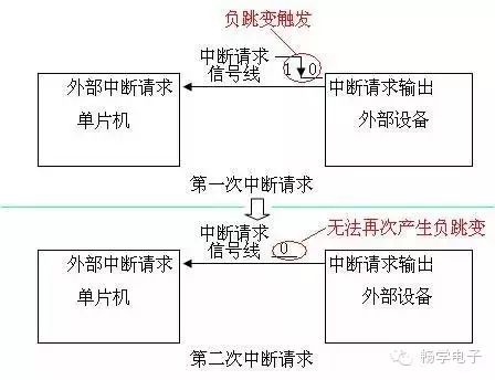
Figure 1: External Device Can Only Generate One Interrupt Request Signal
By modifying the external device’s interrupt request signal, it can be changed from merely outputting a high-to-low transition when an interrupt is needed to first transitioning from high to low, then after a short period, transitioning back to high. This way, every time an interrupt is needed, it can output a negative edge-trigger signal to the microcontroller.
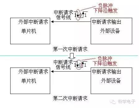
Figure 2: External Device Can Continuously Generate Interrupt Request Signals (Example 1)
Alternatively, the external device can provide an interface through which the microcontroller can perform an interrupt clearing operation, allowing the external device’s interrupt request output pin to return to high.
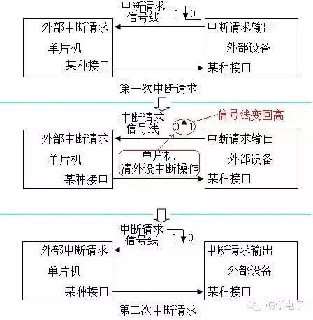
Figure 3: External Device Can Continuously Generate Interrupt Request Signals (Example 2)
External interrupt triggering can also involve special methods, such as external pulse width measurement and external pulse counting. These methods are extensions of the basic triggering methods described earlier; for example, external pulse width measurement involves starting an internal timer when the interrupt signal line changes, measuring the pulse width upon the next change, and restarting the timer. These methods are rarely used and will not be detailed here.
Internal interrupts refer to interrupt signals generated by functional modules within the microcontroller. As long as the functional modules can operate independently within the CPU, they will provide interrupt functionality. Common types of internal interrupts include Timer, UART, and ADC. The workflow for internal interrupts is not much different from that of external interrupts, except that the interrupt request signal is transmitted internally within the microcontroller. The interrupt signal is not the voltage level on the pins but a corresponding flag bit inside a register. Typically, when an internal interrupt generates an interrupt request, the corresponding flag bit is set to 1, and when the CPU responds to the interrupt, it clears this flag bit to 0.
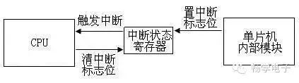
Figure 4: Internal Interrupt Triggering Diagram
The microcontroller does not have a unified standard for handling interrupt flag bits; the specific conventions depend on the microcontroller documentation. Most use a flag bit of 1 to indicate an interrupt has occurred, but some microcontrollers use a flag bit of 0 for the same purpose. Some microcontrollers write whatever is written to the interrupt flag bit, while others require writing 1 or 0 to perform a clear operation, and a few will automatically clear the flag bit just by reading it. If the microcontroller does not want to be triggered by external interrupts, it can simply connect the pin used for the external interrupt signal to a voltage state that does not trigger interrupts. However, internal interrupts cannot change internal wiring, so the microcontroller must have related registers to choose whether interrupts can be triggered. Typically, there is a master control bit in the microcontroller that can control all interrupts, and each interrupt has its own independent control bit to determine its on/off state. If a specific interrupt is to be used, both the master interrupt switch and the corresponding interrupt switch must be turned on.
When the microcontroller generates an interrupt signal, it will trigger the corresponding interrupt. Different interrupt sources will require different response methods; in other words, when different interrupts occur, the microcontroller program must respond differently based on the interrupt source. This is called the interrupt service routine. For instance, if a UART interrupt is triggered by receiving new data, the UART interrupt service routine should read and process the data. If the interrupt is triggered upon ADC conversion completion, the ADC interrupt service routine should read and process the data. Clearing interrupt flag actions are generally completed within the interrupt service routine.
Different interrupt sources require corresponding interrupt service routines. In actual development, not all interrupts will be used, so developers will only write the interrupt service routines they need, meaning some interrupts will not have corresponding service routines. If such an interrupt is triggered, the microcontroller program will run into errors. The independent control bits for interrupts come into play here; by turning off these control bits, the corresponding interrupts will not be triggered.
When the microcontroller powers on, if the control register for whether interrupts are enabled is set to on, there may be cases where interrupts are falsely triggered. If this interrupt does not have a corresponding service routine, the program will crash. Therefore, when the microcontroller powers on, it generally automatically turns off all the flag bits in these registers to avoid false triggers.
The interrupt service routine is part of the microcontroller program, and its specific content is determined by the developer. Thus, the size of the interrupt service routine and its position in the microcontroller program are not fixed. When an interrupt is triggered, the microcontroller needs to know where the interrupt service routine is located in order to execute it. The microcontroller resolves this issue through an interrupt jump table (interrupt vector table).
Although the size of the interrupt service routine and its position in the entire program may not be fixed, as long as the program is burned into the microcontroller system, for that program, the size and position of the interrupt service routine will be fixed. If we make certain agreements regarding memory allocation for the microcontroller program, we can allocate a fixed absolute address specifically for interrupts. During program compilation, the starting address of the interrupt service routine (or the instruction that jumps to the interrupt service routine) will be filled into the space at this fixed absolute address. When an interrupt occurs, the microcontroller first reads the content at this absolute fixed address, and based on the content read, it can jump to the interrupt service routine.
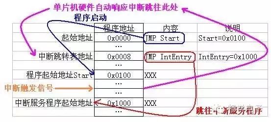
Figure 5: Interrupt Response Diagram
Simple microcontrollers offer a limited variety of interrupts. To simplify the program, each interrupt is assigned a space to store the address of its service routine. This method is not particularly problematic, but as microcontroller technology has evolved, high-end microcontrollers have become increasingly complex. Consequently, some specialized manufacturers have begun to collaborate and share technical resources. For example, ARM utilizes its technological advantages in CPU architecture to provide CPU cores to other manufacturers, who then add functional modules around the ARM core. Most of these functional modules support interrupts.
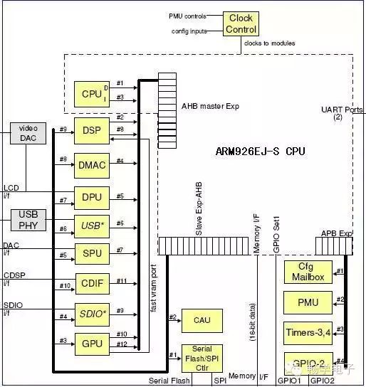
Figure 6: ARM Core Microcontroller Architecture
Different manufacturers design different peripheral functional modules based on the same CPU core, resulting in varying types and numbers of interrupts. However, the method for the CPU to process interrupts remains the same. If we continue the simple microcontroller’s practice of assigning an address space for each interrupt, it becomes problematic as the CPU cannot know how many types of interrupts need to be supported and which modules correspond to which interrupts. Therefore, another method of handling interrupts is adopted: all interrupt addresses are directed to the same one, and all interrupts are numbered sequentially. When an interrupt occurs, the CPU informs the interrupt service routine of the current interrupt number, and the service routine responds accordingly.
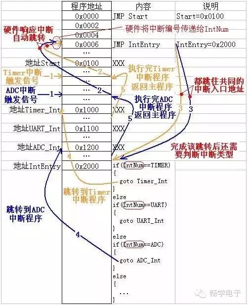
Figure 7: Common Interrupt Entry Response Flowchart
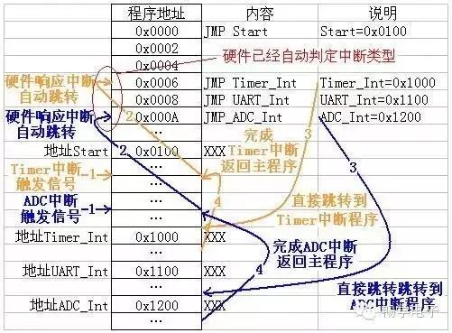
Figure 8: Independent Interrupt Entry Response Flowchart
While using the same interrupt vector address for all interrupts and determining the interrupt type based on the interrupt number solves the problem of general CPU cores not being able to directly correspond to interrupt vector addresses, it also reveals that the response speed of interrupts is slower compared to microcontrollers with independent interrupt vector tables. A microcontroller with an independent interrupt vector table can directly enter the interrupt program with a single jump instruction, while a microcontroller without an independent interrupt vector table must first jump to a common interrupt entry and then determine the interrupt type through code before jumping to the actual interrupt program. C language code exacerbates this situation, so microcontrollers without independent interrupt vector tables generally use assembly lookup methods to speed up interrupt response times.
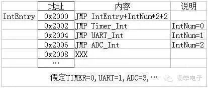
Figure 9: Fast Jump Table for Assembly Interrupts
After the interrupt program is executed, control returns to continue executing the main program. This requires that the interrupt does not alter the running state of the main program. Therefore, the current running state information, such as the location in the program and the current state of the CPU status register, must be saved during the interrupt response. After the interrupt program is completed, these pieces of information can be used to restore the CPU status register to its original state and return to the main program for continued execution. Different microcontrollers may handle this differently; one method is to have hardware completely manage it without requiring program management, while another method is to save state information using specific instructions at designated locations and restore it using corresponding instructions upon return.
Microcontroller interrupts also involve the concepts of interrupt priority and interrupt nesting, but not all microcontrollers support these two functions. Interrupt priority means that different interrupts will have different priority levels. If two interrupts occur simultaneously, the microcontroller will respond to the higher-priority interrupt first. Interrupt nesting refers to the ability of the microcontroller to pause the execution of the current interrupt program to respond to a new interrupt that occurs during the interrupt response. After executing the new interrupt program, it will resume the execution of the current interrupt program. Generally, interrupt nesting allows higher-priority interrupts to interrupt lower-priority interrupt response programs, while interrupts of the same or lower priority cannot interrupt the current interrupt response program.
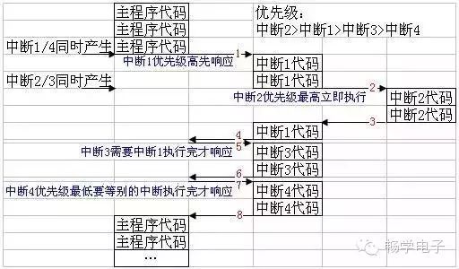
Figure 10: Interrupt Nesting Diagram
Interrupt Steps Explanation:
Step 1: Save the main program state and execute interrupt 1 service program.
Step 2: Save the interrupt 1 service program state and execute interrupt 2 service program.
Step 3: Restore the interrupt 1 service program state and continue executing interrupt 1 service program.
Step 4: Restore the main program state and prepare to continue executing the main program; if there is a new interrupt, the main program cannot continue execution.
Step 5: Save the main program state and execute interrupt 3 service program.
Step 6: Restore the main program state and prepare to continue executing the main program; if there is a new interrupt, the main program cannot continue execution.
Step 7: Save the main program state and execute interrupt 4 service program.
Step 8: Restore the main program state; if no interrupts occur, continue executing the main program.
Some microcontrollers automatically turn off the global control bit for interrupts upon entering an interrupt function, requiring developers to reopen it in the interrupt program; otherwise, all interrupts will be disabled after one interrupt. For the interrupt flag bits, when writing microcontroller programs, it is essential to follow the microcontroller documentation for clearing flag operations; otherwise, a specific interrupt may continuously trigger the same interrupt, preventing the main program from continuing to run.