When it comes to lightweight and high energy-absorbing structures, you might think of automotive crash beams, sports protective gear, or even biomedical implants. Behind these scenarios, a structure known as “Triply Periodic Minimal Surface (TPMS)” is gradually becoming a research focus. A recent study published in Thin-Walled Structures (Volume 217, 2025) deeply explores the “material-topology-orientation” synergistic effect of TPMS structures, unveiling key laws regarding their mechanical performance and energy absorption characteristics using rigid PLA and flexible TPU materials, providing a new basis for customized design.
Main Content
1. Why Study TPMS Structures? Existing Pain Points Await Resolution
TPMS structures are a class of periodic surface structures defined by mathematical equations. With zero mean curvature and high specific surface area, they inherently possess excellent mechanical properties and energy absorption capabilities, showing great potential in fields such as impact protection, aerospace, and biomedicine. However, related research has long had significant shortcomings:
-
Most studies focus on “hard materials” like metals and rigid plastics, with very few examining flexible thermoplastic polymers (such as TPU);
-
There is a lack of systematic analysis on the coupling effects of “material flexibility + structural topology + crystal orientation,” making it difficult to guide customized design for different scenarios.
To address this, the research team selected three classic TPMS topologies (Primitive/P, Gyroid/G, Diamond/D), paired with one rigid material (PLA) and two flexible materials (TPU-95A, TPU-87A), and prepared samples through 3D printing (Fused Filament Fabrication, FFF). They systematically tested the performance of three crystal orientations: [001], [101], and [111], filling this research gap.
2. Experimental Design: Precise Control at Every Step from Structure to Testing
To explore the synergistic effects of “material-structure-orientation,” precise control of experimental variables is essential. The research team paid great attention to detail during the design phase:
1. TPMS Structure: Mathematical Definition + Unified Parameters
All three TPMS structures were generated through strict mathematical implicit functions, with core parameters highly unified:
-
Unit cell edge length of 10mm, forming a 3×3×3 unit cell matrix (final size 30×30×30mm³) to avoid boundary effect interference;
-
The target relative density (structural density / solid material density) is 0.25, ensuring a fair comparison between topologies;
-
Crystal orientation choices [001], [101], [111] (based on Miller indices) cover typical stress directions.
2. Material Selection: A Direct Comparison of Rigid and Flexible
Three typical thermoplastic materials were selected, representing different mechanical properties:
-
PLA (Polylactic Acid): Benchmark for rigid materials, with a Young’s modulus of 2517.5±89.8MPa, but high brittleness and low fracture strain;
-
TPU-95A: Medium flexibility material, with an elastic modulus of 108.2±10.5MPa, balancing rigidity and deformation capability;
-
TPU-87A: High flexibility material, with an elastic modulus of only 24.8±3.2MPa and a fracture elongation of 4.7 (1.8 times that of TPU-95A).
3. 3D Printing: Optimizing Parameters for Material Characteristics
The flexibility of TPU presents significant challenges for 3D printing, leading to issues such as stringing, poor interlayer adhesion, and nozzle clogging. The research team optimized the process accordingly:
-
Temperature Control: PLA printing temperature at 220℃, bed temperature at 55℃; TPU series printing temperature at 215℃, bed temperature at 35℃ to avoid overheating and deformation;
-
Retraction Settings: TPU material retraction length of 2mm to reduce “oozing” during printing;
-
Dehumidification Treatment: TPU dehumidified at 70℃ for 6 hours before printing to prevent moisture absorption leading to nozzle clogging.
4. Testing Methods: Dual Validation through Experiments and Simulations
-
Quasi-static compression tests: Using a universal testing machine, first perform 5 cycles of small strain to eliminate surface defects, then compress to structural collapse at a strain rate of 8.33×10⁻⁴/s;
-
Finite Element Analysis (FEA): Modeling with ABAQUS software, using an elastic-plastic model for PLA and a third-order Ogden hyperelastic model for TPU to accurately simulate the deformation process;
-
Key Indicators: Specific energy absorption (SEA, measuring energy absorption capacity per unit mass), crush force efficiency (CFE, measuring deformation stability), Young’s modulus, platform stress, etc.
3. Core Findings: Three Key Conclusions that Challenge Conventional Understanding
After testing and analyzing 81 samples, the research team drew a series of guiding conclusions, among which three findings are particularly critical:
1. Material Selection: The “Trade-off between Strength and Stability”
The performance of different materials shows significant differentiation, perfectly illustrating the saying “You can’t have your cake and eat it too”:
-
PLA: Strongest energy absorption capability but poorest stability: average SEA of 8.205±0.366 J/g (9 times that of TPU-95A, 23 times that of TPU-87A), but CFE of only 0.777±0.064 (lowest), due to PLA’s brittleness leading to sudden stress drop;
-
TPU-95A: Optimal stability, moderate energy absorption: CFE of 0.923±0.059 (highest), SEA of 0.876±0.072 J/g, achieving “smooth energy absorption” with no risk of fracture due to its superelastic properties;
-
TPU-87A: Excessive flexibility leads to decreased stability: SEA of only 0.356±0.037 J/g, CFE of 0.863±0.064 (lower than TPU-95A), as excessive flexibility can lead to “premature buckling,” compromising energy absorption stability.
2. Topological Structure: Gyroid as the “Stability King,” Diamond for Optimal Energy Absorption
The performance differences among the three TPMS topologies are significant, with each suitable for different scenarios:
-
Gyroid (G) structure: Most stable performance, strongest adaptability: Across all materials and orientations, SEA variation ≤ 16.1%, CFE variation ≤ 2.9%, its nearly isotropic characteristics make it “material-agnostic and orientation-agnostic,” making it the first choice for general design;
-
Diamond (D) structure: Energy absorption champion, directionally optimized: D [001] orientation has the best energy absorption capability among all materials — PLA’s volumetric energy absorption density reaches 3.80 J/cm³, TPU-95A reaches 0.39 J/cm³, TPU-87A reaches 0.15 J/cm³, suitable for scenarios with high energy absorption requirements;
-
Primitive (P) structure: Strongest coupling effect, design requires caution: The same orientation shows “completely opposite” performance in different materials — P [001] has the lowest CFE in PLA (layered collapse) but the highest in TPU (stable deformation); P [101] shows the opposite, with the highest CFE in PLA and the lowest in TPU, requiring precise matching of materials and orientations during design.
3. Printing Quality: Beware of the “Precision Trap” of Flexible Materials
The higher the material flexibility, the more challenging the quality control in 3D printing:
-
Density Deviation: PLA printing density deviates from design by only 1.96%, TPU-95A reaches 2.72%, TPU-87A reaches 4.43%, due to TPU’s high viscosity, which can easily lead to “thinning” or “accumulation” during extrusion;
-
Surface Defects: PLA has a smooth surface with size deviation ≤ 0.1mm; TPU-87A is prone to overfilling (in unsupported overhangs) and stringing, with large interlayer gaps, directly affecting mechanical performance;
-
Topological Impact: D structure has a geometric complexity (sharp edges, fine mesh), resulting in a post-print density that is 8.7%-10.8% higher than the design value, requiring pre-correction during modeling.
4. Application Value: Three Design Recommendations for Engineers
This research not only fills theoretical gaps but also provides clear guidance for practical engineering design. Different scenarios can follow these ideas for solution selection:
-
High energy absorption + Directional stress scenarios (e.g., automotive crash beams): Prioritize D [001] orientation + PLA, leveraging the high energy absorption of D structure and the high strength of PLA to achieve “hard protection”;
-
High stability + Repeated impact scenarios (e.g., sports protective gear, insoles): First choice is G structure + TPU-95A, combining the stability of Gyroid and the superelasticity of TPU-95A to achieve stable energy absorption under multiple impacts, with no risk of fracture;
-
Low stress + Flexible protection scenarios (e.g., medical protective gear, electronic device cushioning pads): Recommend P [001] orientation + TPU-87A, utilizing the high stability of P [001] in TPU and the low modulus of TPU-87A to achieve “soft protection,” avoiding secondary injury to the human body or equipment.
Conclusion
From mathematically defined surfaces to 3D printed entities, from rigid PLA to flexible TPU, this research opens new avenues for the “customized design” of TPMS structures through systematic experiments and clear conclusions. In the future, with advancements in 3D printing technology and the richness of material systems, TPMS structures are expected to achieve “tailored solutions” in more fields, bringing lightweight and high energy-absorbing products into everyday life.
(Original title: Anisotropic mechanical properties and energy absorption of TPMS structures: a comparative study of polylactic acid and thermoplastic polyurethane materials, published in Thin-Walled Structures 217 (2025) 113868)
Image Content
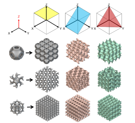 Figure 1: Primitive (P), Gyroid (G), and Diamond (D) TPMS structures (from top to bottom) under [001], [101], and [111] crystal orientations (from left to right) with their corresponding 3×3×3 cell matrices. The Z-axis is the printing direction.
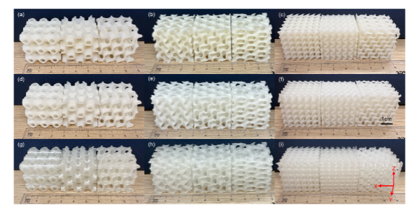 Figure 2: Additive manufacturing samples made from three materials with three different TPMS topologies: Primitive (P, corresponding to a, d, g), Gyroid (G, corresponding to b, e, h), and Diamond (D, corresponding to c, f, i); the three materials used are Polylactic Acid (PLA, corresponding to a–c), Thermoplastic Polyurethane – 95A (TPU-95A, corresponding to d–f), and Thermoplastic Polyurethane – 87A (TPU-87A, corresponding to g–i). In each photo, the crystal orientations from left to right are [001], [101], and [111].
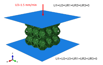 Figure 3: Boundary conditions for nonlinear finite element analysis (FEA)
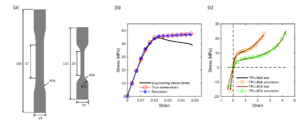 Figure 4: (a) Geometry of tensile samples: left is the Polylactic Acid (PLA) sample (conforming to ASTM D638 standard Type I), right is the Thermoplastic Polyurethane (TPU) sample (conforming to ASTM D638 standard Type IV). All dimensions are in millimeters (mm). (b) Experimental engineering stress-strain curve for Polylactic Acid (PLA), experimental true stress-strain curve, and simulated elastic-plastic true stress-strain curve. (c) Experimental tensile and compressive engineering stress-strain results for Thermoplastic Polyurethane – 95A (TPU-95A) and Thermoplastic Polyurethane – 87A (TPU-87A), along with simulation results fitted with the third-order Ogden model.
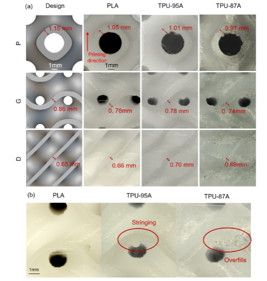 Figure 5: (a) Comparison of TPMS design models and printed samples for Polylactic Acid (PLA), Thermoplastic Polyurethane – 95A (TPU-95A), and Thermoplastic Polyurethane – 87A (TPU-87A): showing Primitive (P), Gyroid (G), and Diamond (D) structures for [001] orientation. (b) Microscopic images of printing details for different materials.
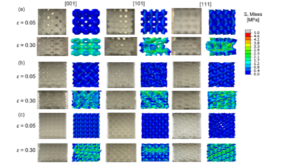 Figure 6: Young’s modulus surface and corresponding Zener ratio for a triply periodic minimal surface (TPMS) unit cell made of Polylactic Acid (PLA) with a relative density of 25%. The structures shown are: (a) Primitive (P), (b) Gyroid (G), (c) Diamond (D).
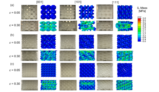 Figure 7: Experimental deformation of Thermoplastic Polyurethane – 87A (TPU-87A) triply periodic minimal surface (TPMS) structures under different orientations ([001], [101], [111]) and finite element analysis (FEA) stress cloud maps: (a) Primitive (P), (b) Gyroid (G), (c) Diamond (D) structures at strain values of \(\varepsilon=0.05\) and \(\varepsilon=0.30\).
Disclaimer
The content published in this article is for informational sharing only, aimed at providing readers with materials for multi-angle thinking. The editor’s level is limited, and the original content only represents original translation; it does not claim copyright of the original text. For infringement, please contact for deletion.
If you are interested in this article, feel free to like, bookmark, and share it with more people. You are also welcome to leave comments and discuss in the comment section!
Original Article:https://doi.org/10.1016/j.tws.2025.113868