System Overview
This system uses the AT89C51 microcontroller as the core controller, integrating the ADC0831 analog-to-digital converter, DAC0808 digital-to-analog converter, DS1302 real-time clock, FM24C64F EEPROM memory, and LGM12641BS1R LCD display to achieve a complete data acquisition, conversion, storage, and display system.
ADC0831 Analog-to-Digital Converter (ADC)
ADC0831 is an 8-bit resolution, serial output successive approximation analog-to-digital converter (SAR ADC) introduced by National Semiconductor. It has been widely used in early microcontroller systems due to its simplicity and low cost.
Main Features
-
Resolution: 8 bits. This means it can divide the analog input voltage into 2^8 = 256 discrete levels, with a resolution of VREF/256.
-
Conversion Time: Typical value is 32μs.
-
Interface Type: Serial SPI compatible interface. It only requires 3 lines (CS, CLK, DO) to communicate with the microcontroller, greatly saving MCU I/O resources.
-
Input Channel: 1 single-ended input channel or 1 differential input. By configuring the pins, its only analog input pin (VIN+) can be measured relative to GND (single-ended) or relative to VIN- (differential).
-
Reference Voltage: External reference voltage (VREF). The reference voltage directly determines the sensitivity and range of the ADC. For example, when VREF=5V, the resolution LSB = 5V / 256 ≈ 19.53mV.
-
Supply Voltage: +5V single power supply.
-
Total Unadjusted Error: ±1 LSB.
DAC0808 Digital-to-Analog Converter (DAC)
DAC0808 (or similar series such as DAC0800, DAC0801) is a classic 8-bit parallel input, current output digital-to-analog converter. It is known for its high speed, high precision, and direct current output characteristics.
Main Features
-
Resolution: 8 bits.
-
Conversion Speed: Very fast, with a typical settling time of 150ns. This means it can convert digital inputs to stable analog outputs in a very short time, suitable for high-speed applications.
-
Output Type: Current output. It outputs a current (Iout) proportional to the digital input value, rather than a voltage. To obtain a voltage output, an operational amplifier (Op-Amp) must be connected in an I-V conversion circuit (usually an inverting proportional amplifier).
-
Interface Type: Parallel interface. The 8-bit digital input value is directly written through data pins (A1-A8), and conversion starts immediately after writing, ensuring fast response.
-
Reference Current: Requires a stable external reference current (Iref). This reference current is typically generated by a reference voltage source (Vref) and a precision resistor (Rref), with the formula
<span>Iref = Vref / Rref</span>. The output full-scale current is<span>Iout = (digital code / 256) * Iref</span>. -
Supply Voltage: Typically uses dual power supplies of ±5V or ±15V to meet the output amplifier’s swing requirements.
-
Compatibility: Output current is compatible with all logic families (e.g., TTL, CMOS).
Hardware Connections
-
ADC0831: P0.0-P0.2 (CS, CLK, DO) – Analog signal acquisition
-
DAC0808: P3.0-P3.7 (A1-A8) – Digital to analog output
-
DS1302: P2.5-P2.7 (RST, SCLK, I/O) – Real-time clock
-
FM24C64F: P0.4-P0.5 (SCL, SDA) – EEPROM storage
-
LGM12641BS1R:
-
P1.0-P1.7 (DB0-DB7) – Data bus
-
P2.4-P2.7 (CS2, CS1, RW, EN) – Control signals
-
Buttons: P0.6-P0.7 – Store and read functions
Code Implementation
#include <absacc.h>
#include <intrins.h>
#include <reg51.h>
#include “HZ.h”
#include “LCD.h”
#include “1302.h”
#include “key.h”
#include “adc0831.h”
uchar time0_count; // time0 counter
// time0 initialization
void time0_init(void)
{
EA = 1;
ET0 = 1;
TMOD = 0x01;
PT0 = 1;
TH0 = 0x3C;
TL0 = 0xB0;
TR0 = 1;
}
void main(void)
{
I_init();
InitLCD();
time0_init();
show_hz();
show_date_time();
while(1)
{
KeyScan();
}
}
void time0_interrupt(void) interrupt 1
{
TH0 = 0x3c;
TL0 = 0xb0;
time0_count++;
if(time0_count==20)
{
time0_count=0;
show_date_time();
a = readadc();
b1 = a/100;
b2 = (a%100)/10;
b3 = (a%100)%10;
show_ad();
P3 = a; // Perform digital-to-analog conversion
}
}
Proteus Simulation Instructions
-
Create a Proteus project and add the following components:
-
AT89C51 Microcontroller
-
ADC0831 Analog-to-Digital Converter
-
DAC0808 Digital-to-Analog Converter
-
DS1302 Real-Time Clock
-
FM24C64F EEPROM
-
LGM12641BS1R LCD Display
-
Buttons and pull-up resistors
Connect the components according to the above connection instructions
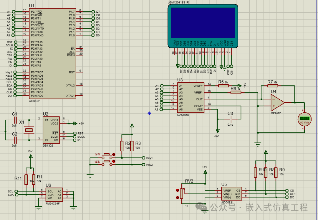
Set the reference voltage of the ADC0831 to 5V
Compile the code and generate the HEX file
Load the HEX file in the properties of the AT89C51
Run the simulation and observe the time and voltage values displayed on the LCD
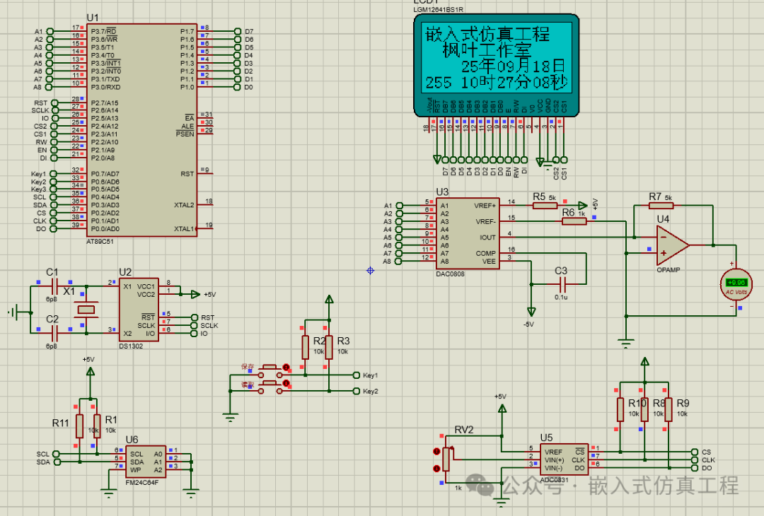
Test the button functions: press the store button to save the current voltage value, and press the read button to display the saved voltage value
System Functions
-
Real-time clock display: Read the time from the DS1302 and display it on the LCD
-
Analog signal acquisition: Acquire analog signals through the ADC0831 and convert them to digital values
-
Digital to analog: Convert digital values back to analog signals through the DAC0808
-
Data storage: Store the acquired voltage values through the FM24C64F
-
Data display: Display time, voltage, and other information through the LGM12641BS1R
-
User interaction: Implement storage and reading functions through buttons
This system demonstrates how to integrate various peripherals into a microcontroller system to achieve complex data acquisition, processing, and display functions.
Welcome to follow (operation reference article: Send a message to the public account), click the blue text at the top “Embedded Simulation Project” or long press to identify the QR code to follow
Reply in the public account
5137
After receiving, automatically send the link to this project’s Keil project and simulation project (free project).