Modern Traffic Signal Control Machines

General Composition of Modern Traffic Signal Machines
Traffic signal control machines refer to all the electronic and mechanical components installed in cabinets that control the operation of traffic lights, including the cabinets themselves. With technological advancements, traffic signal control machines have evolved from purely mechanical controllers to modern traffic signal control machines centered around microprocessors. Modern traffic signal control machines are divided into software and hardware components, with the functionality primarily determined by software, while hardware mainly provides physical protection and executes code instructions.
Although the physical composition of modern traffic signal control machines varies based on different design philosophies and specifications, the basic functional unit division of traffic signal control machines remains universal. Based on the different functions they perform, traffic signal control machines are typically divided into the following functional units.
1.Main Control Unit
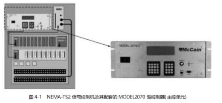
The main control unit is located inside the traffic signal control machine cabinet and possesses typical embedded computer characteristics, realizing core traffic signal control logic, issuing commands, performing necessary data calculations, and parsing communication protocols. The main control units of NEMA-TS2 (a standard for traffic signal control machines established by the National Electrical Manufacturers Association) signal controllers and certain domestic open-source signal controllers are shown in Figures 4-1 and 4-2.
The main control unit typically implements the following functions.
(1) System initialization self-check, usually including self-check of device status and parameter checks;
(2) Communication with other functional units, such as sending lamp drive commands to the lamp driver unit and obtaining necessary feedback on lamp group driving voltage and current data;
(3) Implementing certain control logic, such as scheduling according to time tables, adaptive scheme calculations based on detector data, or inductive control;
(4) Communication with field devices to realize necessary on-site control functions, such as communicating with manual panels for on-site manual control or communicating with field terminal devices to change operational schemes;
(5) Communication with the central platform to achieve regional linkage, fault reporting, and other functions.
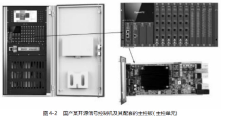
The main control unit generally adopts an embedded computer platform with high reliability and sufficient computing power and interface expansion capabilities available at the time of design. For example, the PSCⅡ signal controller produced by Philips in the 1990s used a 10MHz 80188 processor, expanded with 32KB of RAM and 64KB of ROM, and used a modem with a baud rate of 300 for long-distance communication. This limited-capacity processing platform could only handle relatively simple business logic; however, most newly designed signal controllers now use ARM architecture embedded chips with clock frequencies exceeding 200MHz, with memory and file systems typically measured in MB or even GB. For instance, a certain domestic open-source signal controller’s main control unit uses an automotive-grade ARM Cortex A9 processor with a clock frequency of 1GHz, 1GB of memory, and an 8GB file system, providing multiple Gigabit Ethernet interfaces for communication.
2.Lamp Driver Unit
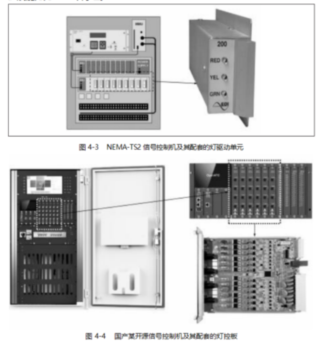
The lamp driver unit is installed inside the traffic signal control machine cabinet and drives the lamp groups according to commands from the main control unit, enabling them to output corresponding statuses. The lamp driver unit typically has functions for detecting lamp voltage and current or lamp power, to facilitate fault detection logic for identifying critical faults such as green conflicts, simultaneous red and green lights, and complete red light outages. The lamp driver units of NEMA-TS2 signal controllers and certain domestic open-source signal controllers are shown in Figures 4-3 and 4-4.
According to the general application scenarios of traffic signals, the lamp driver unit usually forms a lamp group with three channels: red, yellow, and green. The number of lamp groups that a single traffic signal control machine can support is an important design indicator. For example, Tyco’s Eclipse traffic signal controller can support 8 lamp groups with a single lamp driver unit, and each traffic signal control machine can expand to a maximum of 4 lamp driver units, giving it a maximum expansion capacity of 32 lamp groups. A certain domestic open-source signal controller can support 4 lamp groups with a single lamp driver unit, and a single logic box can expand to 10 lamp driver units, allowing for a maximum of 4 logic boxes to be cascaded, resulting in a maximum expansion capacity of 40 lamp groups in a non-cascaded state and 160 lamp groups in a cascaded state.
For signal controllers with insufficient lamp group expansion capabilities, construction practices typically involve directly connecting the same phase lamp groups, which is not conducive to flexible adjustments in phase composition later on, and it is often challenging to accurately detect faults in individual lamps within connected lamp groups.
The output voltage, output current, or output power detection functions of the lamp driver unit are the most important means of fault determination for the signal controller. For example, the determination of green conflicts and simultaneous red and green lights is based on the output voltage of the corresponding channel in the lamp group. When the lamp driver units corresponding to the green lights of the conflicting channels all detect effective voltage output, it is determined that a green conflict has occurred; similarly, when both the red and green lights in the same lamp group detect effective voltage output, it is determined that simultaneous red and green lights are present. The determination of complete red light outage faults is based on the output current or output power of the corresponding channel in the lamp group. When the lamp driver unit corresponding to the red light detects effective output voltage, but the lamp current detection indicates no current or the lamp power detection indicates no power output, it can be concluded that a complete red light outage fault has occurred.
Voltage detection of lamps is typically done by directly extracting voltage feedback signals from the lamp output terminals to a voltage comparison circuit or entering AD sampling, with the program determining whether the sampling results reach the threshold.
The common methods for detecting lamp current currently include current transformer methods or resistance sampling methods. The advantage of the current transformer method is its simplicity, while its drawback is that it cannot detect the DC output current of lamps. The resistance sampling method can meet the detection needs of both AC and DC lamps, but for AC lamps, the detection circuit reference ground must be set to the AC live wire, which requires a higher level of circuit design. The lamp driver unit can be abstractly understood as a switch; according to electrical safety regulations, the switch must be wired in series with the AC live wire input to ensure that the lamp is at zero potential when the switch is opened. The resistance sampling method cannot achieve direct electrical isolation like the current transformer, so its accompanying logic circuit must use the AC live wire as the reference ground, while circuits that can be accessed by general personnel must use the ground as the reference ground, thus the high-voltage isolation issue between the current sampling circuit and general digital circuits must be properly handled.
Due to the fact that some signal lamp fixtures currently use built-in switch power supply designs to ensure that lamp output brightness is not affected by power supply voltage fluctuations, their external impedance characteristics are capacitive rather than the purely resistive characteristics of traditional incandescent lamps. Simply measuring voltage and current cannot accurately reflect the actual power output of the lamp group. To solve this problem, lamp power detection has emerged, which requires high-frequency sampling of voltage and current, demanding high processing capabilities and presenting significant design challenges.
3. Yellow Flash Control Unit
The yellow flash control unit is installed inside the traffic signal control machine cabinet, independent of the lamp driver unit. When the main control unit of the signal controller cannot operate normally due to faults or maintenance, it realizes the function of controlling the signal controller to output a yellow flash state.
The yellow flasher serves as the safety baseline for traffic signal controllers and typically works in conjunction with fault detection units and necessary electrical components, ensuring that once a critical fault that affects system safety is detected, the control authority of the main control unit is immediately revoked, and the output authority of the signal controller lamp groups is transferred to the yellow flasher, maintaining the intersection in a yellow flash state. Its switching principle is illustrated in Figure 4-5, generally achieved by the main relay and yellow flash relay working together.
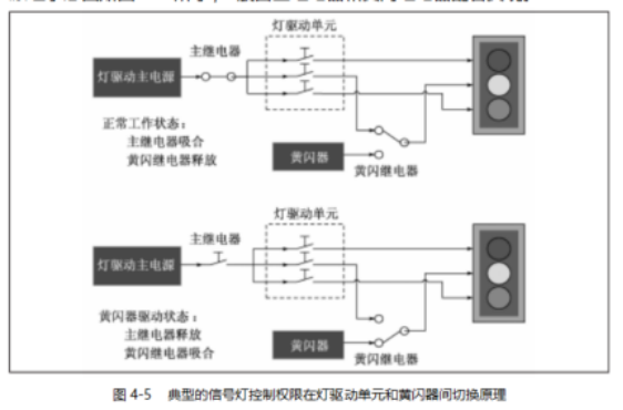
When the lamp group is normally controlled by the lamp driver unit, the main relay is engaged, and the yellow flash relay is released. At this point, the lamp driver unit’s driving circuit receives power from the lamp driver’s main power supply and drives the lamp group to output red, yellow, and green as needed, with the yellow light being controlled directly by the lamp driver unit through the yellow flash relay.
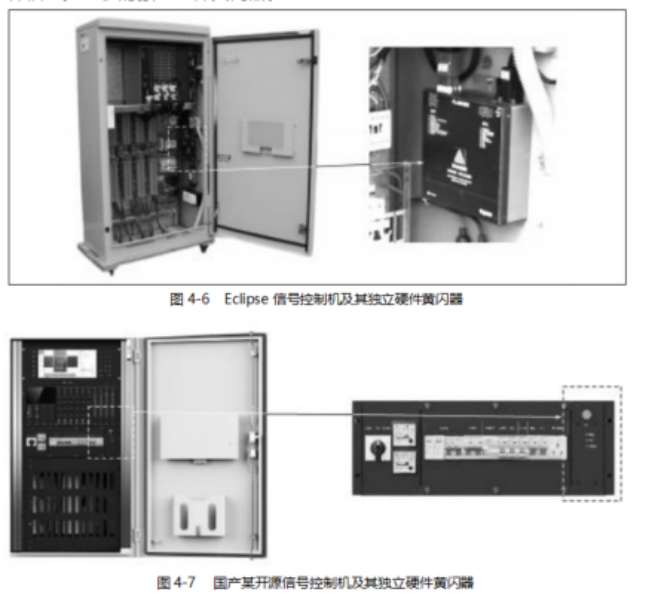
When it is necessary to switch to the hardware yellow flash state controlled by the yellow flasher, the main relay is released, and the yellow flash relay is engaged. At this point, the driving circuit of the lamp driver unit has no power input and cannot output externally; the yellow light is now connected to the yellow flasher and is directly controlled by it. Figures 4-6 and 4-7 illustrate two types of signal controllers with independent hardware yellow flashers.
In actual system design, there are generally two methods for yellow flash control: the completely independent yellow flasher mode and the semi-independent yellow flasher mode. The completely independent mode is shown in Figure 4-8, while the semi-independent mode is shown in Figure 4-9.
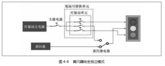
In the completely independent horizontal design of the yellow flasher, the yellow flasher is typically deployed as an independent module, not merged with other functional units. By coordinating the main relay, yellow flash relay, and accompanying electrical lines within the cabinet, it achieves switching between normal system control and yellow flasher control for lamp group driving. The advantage of this approach is that during system maintenance phases (such as replacing the logic box), the intersection can maintain a yellow flash without extinguishing, while the drawback is that the electrical lines rely on hard wiring, resulting in higher costs.
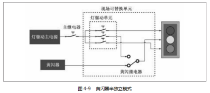
In the semi-independent horizontal design of the yellow flasher, the yellow flasher is typically a relatively independent board within the logic box or designed in conjunction with other functional boards in the logic box, with the yellow flash relay integrated on the lamp driver unit board. The advantage of this approach is that it transfers the electrical connection complexity to the PCB, reducing the complexity of electrical wiring that needs to be manually arranged within the cabinet, lowering costs, and simplifying the overall machine design. However, during system maintenance phases (such as replacing the logic box), the intersection can only remain in an off state.
The choice between these two implementation methods is usually based on system design requirements, with the semi-independent yellow flash scheme often adopted for cost-effectiveness, while the strictly independent yellow flash scheme is chosen for safety and maintainability.
4.Fault Detection Unit
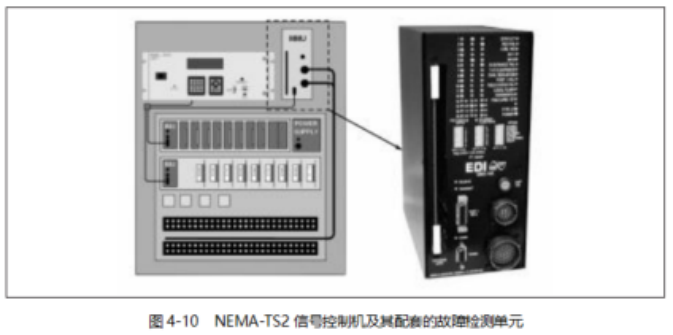
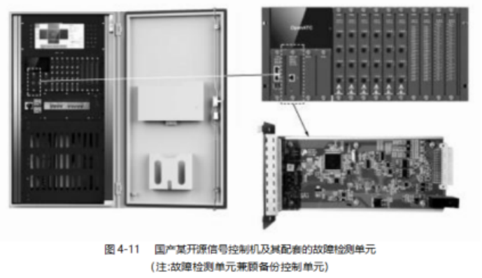
The fault detection unit is installed inside the traffic signal control machine cabinet and possesses the core fault detection capabilities of the signal controller, or has core fault judgment capabilities and can collaborate with other functional units to realize the core fault detection function of the signal controller. The fault detection units of NEMA-TS2 signal controllers and certain domestic open-source signal controllers are shown in Figures 4-10 and 4-11.
The faults that the fault detection unit must typically detect include the following:
(1) Green conflict faults;
(2) All red lights in the signal group are extinguished;
(3) Red and green lights in the signal group are lit simultaneously;
(4) Other serious faults affecting road traffic safety.
Selectable detected faults include the following:
(1) Yellow light and green light faults;
(2) Communication faults;
(3) Detector faults;
(4) Phase switching protection time faults;
(5) Other faults affecting the normal operation of the signal controller. The design methods of the fault detection unit typically include the following:
(1) Directly integrated into the main control unit, represented as a software module;
(2) Merged with certain boards in the system, relatively independent of the main control unit;
(3) A completely independent fault detection unit.
Method (1) is the typical approach for low-end signal controllers, where fault detection is a software function of the main control unit, reducing additional hardware costs and being economically viable. However, theoretically, if the main control unit’s program fails, the fault detection function will also fail, posing significant safety risks.
Method (2) makes the fault detection function relatively independent of the main control unit, allowing the fault detection unit to be an independent embedded computer system or a low-code component that requires the main control unit to set detection rules during the startup phase. Compared to method (1), safety is greatly improved.
Method (3) allows the fault detection function to be completely independent, not merged with other functional boards. The fault detection unit typically has an independent parameter configuration module or obtains detection rules via communication. This type of fault detection unit can typically detect a more comprehensive range of fault types, providing high overall system safety.
5.Backup Control Unit
The backup control unit takes over system control functions when the main control unit fails or is undergoing maintenance upgrades, ensuring that the system continues to operate in a fixed cycle mode without entering a yellow flash state. The backup control unit can be an independent module or integrated into the fault detection unit or other reasonable system components.
The backup control function is typically implemented by a board with an intelligent processor. Traditional signal controllers generally only have the main control unit equipped with sufficiently intelligent processing capabilities, with few designs incorporating backup control functions. However, with the miniaturization and integration of intelligent processors, many functional boards themselves now possess good intelligent processing capabilities, leading to the practical application of backup control units in some signal controller products. This is typically manifested in the event of a main board failure or temporary functional failure due to maintenance upgrades, where a unit with an intelligent processor in the system takes over control and can smoothly transition back to the main control unit’s normal state once it recovers. A well-designed backup control unit should ensure sufficient detection capabilities for core faults during the control system period and can switch the system to a yellow flash state when a core fault occurs.
The backup control unit of a certain domestic open-source signal controller is integrated with the fault detection unit (see Figure 4-11). When the main control unit is functioning normally, it learns in real-time the drive commands issued by the main control unit and saves the learned commands of a complete cycle as a backup control scheme. When it determines that the main control unit has failed, it first drives all field lamp groups that have output green lights into a yellow flash state and transitions to a full red state, clearing the intersection, and then begins driving the lamp groups according to the latest learned cycle scheme. During this period, the core fault detection function remains effective. Once the main board recovers, the backup control unit communicates with the main board to ensure that after completing a full cycle, control authority is returned to the main control unit.
6.Input/Output Unit
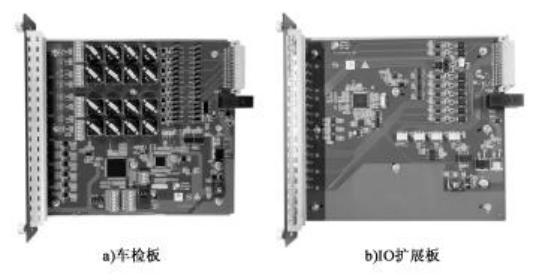
In addition to lamp group outputs, traffic signal controllers typically have a large number of input/output signal requirements, such as pedestrian buttons, bus priority requests, detector signals, countdown communication signals, etc. These signals usually manifest as simple IO requirements or communication requirements. This necessitates that the signal controller can flexibly expand IO signals and communication interfaces, with the input/output unit fulfilling this functional requirement. The vehicle detection board and IO expansion board of a certain domestic open-source signal controller are shown in Figure 4-12.
Recommended Reading
For a more comprehensive understanding, it is recommended to read “Modern Traffic Signal Control Systems,” which brings together the theoretical and practical experiences of numerous experts and scholars engaged in traffic signal control teaching, research, management, and application. Many of the main contents are included in this article, reflecting the state of traffic signal control development and construction needs in China, filling the theoretical research gap in modern traffic signal control, and providing a theoretical basis for cultivating talents in the traffic signal control field.
