Click the blue text to follow us
Author | Juyiyun Drone
Produced by | Juyiyun Drone

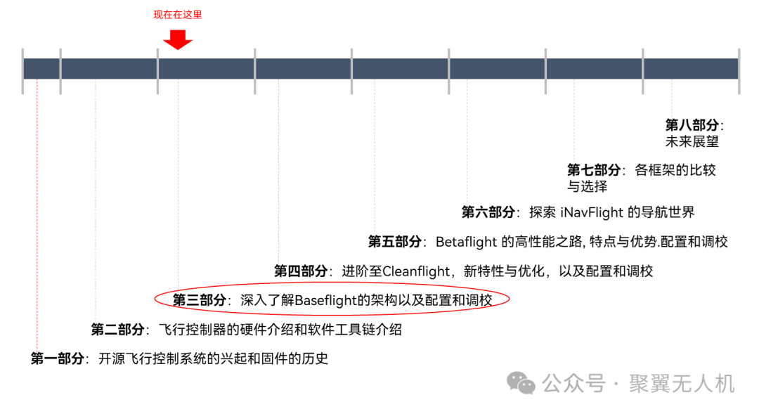
The Open Source Flight Control Series consists of articles analyzing the open-source flight control system – the Flight series project. If you like it, remember to follow us so you can receive update notifications immediately. This series starts from Baseflight to Cleanflight, as well as two derivatives based on Cleanflight: Betaflight and iNavFlight.

This article is the third part of the series, focusing on the program analysis of the main.c file in the src folder.
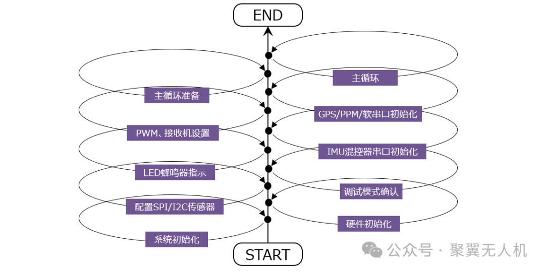
Baseflight is an open-source flight controller firmware widely used in multirotor aircraft and other remote-controlled models. One of its core files, main.c, is responsible for initializing the system, configuring various hardware resources, and starting the main loop to handle flight control logic. This article will provide a detailed analysis of the content and workflow of the main.c file, helping developers better understand how to build and debug similar embedded control systems.
01
Initialization Stage
1.1 Header File Inclusion and Global Variable Definitions
#include "board.h"
#include "mw.h"
#include "telemetry_common.h"
core_t core;
int hw_revision = 0;
extern rcReadRawDataPtr rcReadRawFunc;
● Header Files: Introduces functions and structures defined elsewhere in the project. board.h contains configurations specific to the hardware board; mw.h may relate to multirotor control logic interfaces.
● Global Variables:
core_t core; is an instance of a core control structure used to store system state and other important information.
hw_revision is used to store the hardware version number.
● External Function Pointer: rcReadRawFunc points to the function for reading raw data from the receiver.
1.2 Serial Communication Redirection Setup
#ifdef USE_LAME_PRINTF
static void _putc(void *p, char c) {
    (void)p;
    serialWrite(core.mainport, c);
}
#else
int fputc(int c, FILE *f) {
    while (!isSerialTransmitBufferEmpty(core.mainport));
    serialWrite(core.mainport, c);
    return c;
}
#endif
This code provides two different character output implementations based on whether the USE_LAME_PRINTF macro is defined. One is a simplified version _putc, which ignores extra parameters and sends characters directly; the other is the standard version fputc, which ensures that the serial buffer is empty before sending each character.
1.3 System Initialization
int main(void) {
    uint8_t i;
    drv_pwm_config_t pwm_params;
    drv_adc_config_t adc_params;
    bool sensorsOK = false;
    initEEPROM();
    checkFirstTime(false);
    readEEPROM();
    SetSysClock(mcfg.emf_avoidance);
    if (hse_value == 8000000)
        hw_revision = NAZE32;
    else if (hse_value == 12000000)
        hw_revision = NAZE32_REV5;
    systemInit();
    #ifdef USE_LAME_PRINTF
    init_printf(NULL, _putc);
    #endif
    if (feature(FEATURE_SERIALRX)) {
        switch (mcfg.serialrx_type) {
            case SERIALRX_SPEKTRUM1024:
            case SERIALRX_SPEKTRUM2048:
                spektrumBind();
                break;
        }
    }
    delay(100);
    activateConfig();
}
● Initialize EEPROM and check for first boot: Ensure configurations are loaded correctly.
● Configure System Clock: Determine hardware revision based on HSE value and set appropriate clock frequency.
● System Initialization: Includes initialization of peripherals such as IMU, PWM, ADC, I2C, etc.
● Receiver Type Detection and Initialization: Select appropriate decoding method for the receiver based on configuration (e.g., Spektrum).
● Brief delay and activate configuration: Ensure all initialization is complete before entering normal operation mode.
02
Further Initialization and Function Activation
#ifndef CJMCU
if (spiInit() == SPI_DEVICE_MPU && hw_revision == NAZE32_REV5)
    hw_revision = NAZE32_SP;
#endif
if (hw_revision != NAZE32_SP)
    i2cInit(I2C_DEVICE);
adcInit(&adc_params);
if (feature(FEATURE_VBAT))
    batteryInit();
initBoardAlignment();
sensorsSet(SENSORS_SET);
sensorsOK = sensorsAutodetect();
#ifdef PROD_DEBUG
productionDebug();
#endif
if (!sensorsOK)
    failureMode(3);
LED1_ON;
LED0_OFF;
for (i = 0; i < 10; i++) {
    LED1_TOGGLE;
    LED0_TOGGLE;
    delay(25);
    BEEP_ON;
    delay(25);
    BEEP_OFF;
}
LED0_OFF;
LED1_OFF;
imuInit(); // Mag is initialized inside imuInit
mixerInit(); // this will set core.useServo var depending on mixer type
serialInit(mcfg.serial_baudrate);
● SPI and I2C Initialization: Initialize the respective buses based on hardware version.
● Sensor and Battery Management Initialization: Ensure all necessary sensors are configured correctly.
● Production Debugging and Failure Mode Handling: Execute relevant tests if production debugging is enabled; enter safe mode if sensor initialization fails.
● LED and Buzzer Indication: Signal startup completion by blinking LEDs and sounding a buzzer.
● IMU and Mixer Initialization: Prepare data and parameters required for attitude estimation and motor control.
03
PWM Configuration and Receiver Settings
pwm_params.idlePulse = 0; // brushed motors
pwm_params.syncPWM = feature(FEATURE_SYNCPWM);
pwm_params.fastPWM = feature(FEATURE_FASTPWM);
pwm_params.servoCenterPulse = mcfg.midrc;
pwm_params.failsafeThreshold = cfg.failsafe_detect_threshold;
switch (mcfg.power_adc_channel) {
case 1:
    pwm_params.adcChannel = PWM2;
    break;
case 9:
    pwm_params.adcChannel = PWM8;
    break;
default:
    pwm_params.adcChannel = 0;
    break;
}
pwmInit(&pwm_params);
core.numServos = pwm_params.numServos;
● PWM Parameter Configuration: Set features such as synchronized PWM, fast PWM, etc., based on configuration options and initialize PWM output.
● Receiver Settings: Choose the appropriate decoding method based on the receiver type (e.g., PWM, PPM, or serial protocol).
04
Functional Module Initialization
#ifndef CJMCU
gpsInit(mcfg.gps_baudrate);
#endif
if (feature(FEATURE_PPM))
    core.numRCChannels = MAX_PPM_INPUTS;
if (feature(FEATURE_SOFTSERIAL)) {
    setupSoftSerialPrimary(mcfg.softserial_baudrate, mcfg.softserial_1_inverted);
    setupSoftSerialSecondary(mcfg.softserial_2_inverted);
}
if (feature(FEATURE_TELEMETRY))
    initTelemetry();
● GPS Initialization: Enable the GPS module based on configuration.
● PPM and Soft Serial Function Activation: Configure PPM input or soft serial ports as needed.
● Telemetry Function Initialization: Support flight data transmission to the ground station.
05
Main Loop
previousTime = micros();
if (mcfg.mixerConfiguration == MULTITYPE_GIMBAL)
    calibratingA = CALIBRATING_ACC_CYCLES;
calibratingG = CALIBRATING_GYRO_CYCLES;
calibratingB = CALIBRATING_BARO_CYCLES;
f.SMALL_ANGLE = 1;
while (1) {
    loop();
#ifdef SOFTSERIAL_LOOPBACK
    if (loopbackPort1) {
        // Process loopback for softserial port 1
    }
    if (loopbackPort2) {
        // Process loopback for softserial port 2
    }
#endif
}
● Timestamp Recording and Calibration Parameter Initialization: Prepare for subsequent state estimation and control law calculations.
● Enter Infinite Loop: Call the loop() function to handle real-time tasks such as sensor data reading and state estimation. If soft serial loopback testing is enabled, handle the related logic here.
The loop() in the main loop is the main content after takeoff, and it is located in mw.c, which we will analyze in subsequent articles.
06
Error Handling
void HardFault_Handler(void) {
    writeAllMotors(mcfg.mincommand);
    while (1);
}
● Hard Fault Interrupt Handling: When a severe error occurs, set all motors to the minimum command value (usually to shut down the motors), then enter a dead loop waiting for a reset or other intervention.
07
Conclusion

Through the detailed analysis of the main.c file, we can see that it is not only responsible for system initialization but also contains the startup process of the core control logic. Each step has its specific purpose, from hardware configuration to sensor initialization, and finally to the core control loop, ensuring that the flight controller can operate efficiently and stably. This structured programming approach not only improves the readability and maintainability of the code but also lays a solid foundation for future expansion.
END
If you like it, remember to follow us, and feel free to like, share, and comment!
Disclaimer: Images and materials are sourced from publicly available information on the internet, and this writing is intended to convey industry information. If there are inaccuracies, please feel free to correct them. If there is any infringement, please add the author’s WeChat to delete the article!