Click the blue text above
Follow us!

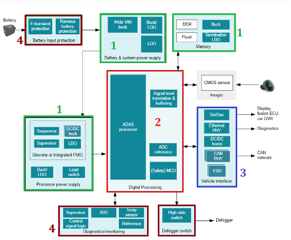
Autonomous driving technology, as an effective way to enhance travel safety and efficiency, has received widespread attention from the automotive and related industries. With the increasing maturity of computer vision systems, the front camera has become an economical, effective, and indispensable part of autonomous driving systems.
This article will deeply analyze the power supply module of the front camera system and detail the TI cost-effective star products, providing convenience for the design selection of the camera.

Figure 1: Block diagram of the front camera system
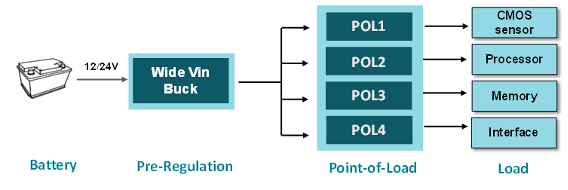
The camera power supply system, as shown in Figure 2, generally takes power from the battery and converts the voltage to an intermediate voltage of 5V/3.3V after one level of conversion. Then, it converts to the voltage required by the load after the second level of voltage conversion. Generally speaking, based on the use and installation scenarios of the onboard camera, the front camera power supply system typically needs to meet the following three requirements:
(1) As small a size as possible;
(2) Good thermal performance;
(3) Easy to use and support subsequent programming expansion.
The following will focus on these three points, providing a detailed introduction to the solutions and star products provided by TI for both the first-level (Pre-regulation) power supply and the second-level (POL) power supply.

Figure 2: Front camera power supply system block diagram
1. First-level (Pre-regulation) Power Supply
Passenger cars are generally equipped with a 12V battery, while commercial vehicles are equipped with a higher 24V battery. Due to the high voltage spikes during the car’s start-up, in order to improve the stability of the power supply, the input voltage range of chips directly connected to the battery usually reserves a large voltage margin. TI recommends the following wide-input Buck chip star products for 12/24V batteries.
Table 1: First-level power supply Buck selection table
Taking the LM7600X-Q1 series synchronous buck chip as an example, this series:
-
Provides Pin-to-Pin selection of different current levels, facilitating subsequent product upgrades;
-
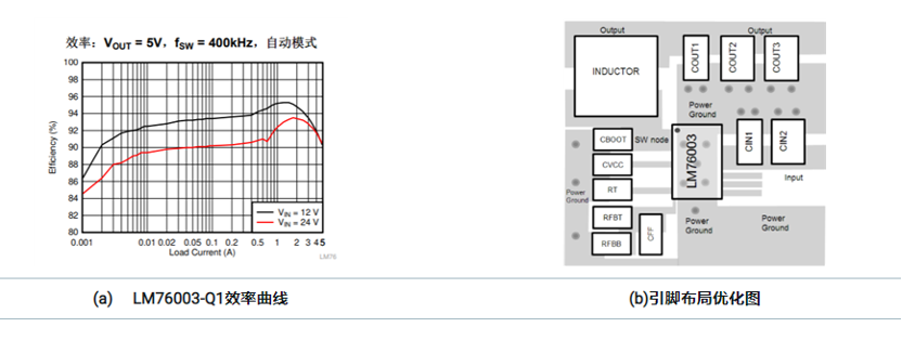
Can seamlessly switch between PFM and PWM modes, improving efficiency at light loads (LM76003-Q1 achieves a maximum efficiency of 95%, as shown in Figure 3 (a)); and has a low on-resistance, ensuring high efficiency;
-
The peripheral circuit is simple, and the pins are designed to simplify PCB layout, providing excellent EMI (CISPR25) and thermal performance, as shown in Figure 3(b)。

Figure 3: Important parameter diagram of LM76003-Q1
2. Second-level Power Supply (POL)
2.1 CMOS Sensor Power Supply
CMOS sensors are very sensitive to noise, especially the AVDD supply ripple noise directly affects image quality and can even cause image distortion. Therefore, the AVDD level of the sensor is generally powered by an LDO with extremely low output noise. Moreover, the EMI and thermal performance of the power supply module also affect the final image quality. TI provides three reliable CMOS power supply solutions based on the integration level of the scheme.
(a) Integrated Solution:PMIC
(TPS65000-Q1/TPS650320-Q1)
Taking TPS65000-Q1 for powering a certain brand of CMOS sensor as an example, TPS65000-Q1 provides two high-precision output LDOs and one high-efficiency Buck, with adjustable input, capable of meeting the needs of various brands with different power rails. The buck frequency can reach as high as 2.5MHz, effectively reducing the size of passive components such as inductors, thereby shrinking the overall module size.
Figure 4: Integrated power supply solution
(b) Semi-integrated Solution — LDO + Dual Buck
The advantage of the semi-integrated solution is that it can optimize PCB layout design based on the installation position of the CMOS sensor, providing high flexibility.

Figure 5: Semi-integrated power supply solution
This solution offers the highest cost performance, and there are many chip options available. The star products of TI for automotive LDOs and dual Buck are shown in the following table.

Table 2: Selection table of star products for CMOS sensor power supply
(c) Discrete Solution — LDO + BUCK*2
The discrete solution is generally lower in overall price, but due to the increased number of chips, it poses great difficulties for the compact layout of the camera module. Therefore, it is generally not recommended.
Since the processor of the front camera integrates modules such as GPU, Safety MCU, image signal processor ISP, and Ethernet interface, the power supply requirements are numerous and vary for each power rail. TI has customized PMIC power supply solutions for various processors. Taking the commonly used PMIC chip in processors — TPS6594-Q1 as an example:
-
TPS6594-Q1 integrates 5 Buck channels and 4 LDOs (including one ultra-low noise LDO);
-
It has low EMI noise and good thermal performance, with fewer peripheral circuits and ease of use;
-
The remaining Buck channels from the PMIC can also be used to power memory, effectively reducing the overall solution size.
TI has customized PMIC power supply solutions for different processors (TDA4/Mobileye Qx/Xilinx/NXP, etc.) as shown in the following table.

Table 3: Processor power supply PMIC selection table
Conclusion
TI can provide a very complete front camera power supply solution,high cost performance, low electromagnetic interference, able to streamline module design, while meeting the thermal performance of the module and reducing the overall solution size, providing a perfect solution for your front camera.
For more online technical support, please visit the TI E2E™ Chinese support forum (e2echina.ti.com).

“Turn, comment, like, collect + look”, more interaction can help you receive our latest news in a timely manner!

Click “Read the original text” to learn more about LM76003-Q1 product details