

Microcontroller The minimum system consists of the external connections of the chip, including the clock circuit, reset circuit, and power supply, forming a basic application system. It mainly includes the clock circuit and reset circuit.
The microcontroller consists of a central processing unit (including some special function registers), internal RAM, program memory, various peripherals (I/O ports, timers, serial interfaces, interrupt handling circuits, etc.), corresponding control registers, clock circuit, reset circuit, and other components.
The microcontroller, also known as a single-chip microcontroller, is not a chip that completes a specific logical function, but integrates a computer system onto a single chip. It is equivalent to a miniature computer, lacking only I/O devices compared to a full computer. In summary, a single chip constitutes a computer. Its small size, light weight, and low cost provide convenient conditions for learning, application, and development.
When working, the microcontroller requires some basic and essential peripheral circuits, including the clock circuit and reset circuit. Additionally, the microcontroller must execute programs, so the microcontroller system must have a program memory capable of storing programs. Microcontrollers without on-chip program memory (such as the 8031 microcontroller) must extend to external program memory. This section will introduce the functions and design methods of the clock circuit and reset circuit.
1. Clock Circuit
The clock circuit is shown in Figure 2-11, where C1 and C2 are matching capacitors. If an external crystal oscillator is connected, a 30pF ceramic capacitor is generally selected. In this circuit, the frequency range of the crystal oscillator is from several hundred kilohertz to several tens of megahertz. The function of the clock circuit is to generate a stable clock oscillation signal, which acts like a metronome to coordinate the unified operation of all components of the microcontroller.
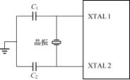
Figure 2-11 Clock Circuit of the Microcontroller
2. Clock Signal
Figure 2-12 shows the waveform of the clock signal generated by the circuit in Figure 2-11. Among them: ① A beat P is a cycle of the crystal oscillator; ② A state cycle S contains two beats, the former beat is P1, and the latter beat is P2; ③ A machine cycle contains 6 state cycles S, that is, S1~S6; ④ Instruction cycle is the number of machine cycles consumed to execute one instruction. The instruction cycle of the MCS-51 microcontroller is usually 1~4 machine cycles.
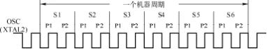
Figure 2-12 Clock Signal Waveform
The relationships between the crystal oscillator oscillation period, machine cycle, state cycle, and crystal oscillator frequency fosc are: crystal oscillator oscillation period = 1/fosc, state cycle = 2/fosc, and machine cycle = 12/fosc. For example, if the crystal oscillator frequency is 12MHz, then the machine cycle is 1μs.
Reset Circuit
1. Function of Reset
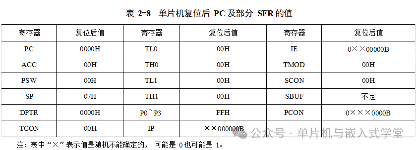
Reset is the initialization operation of the microcontroller and the first operation after the microcontroller is powered on. After the reset, the program counter (PC) of the microcontroller is set to 0000H, causing the microcontroller to fetch instructions from the memory unit at address 0000H in the program memory and execute that instruction. Additionally, after reset, the values of most special function registers of the microcontroller are predetermined, as shown in Table 2-8.
2. Design of Reset Circuit
The RST pin is the input terminal for the reset signal of the microcontroller, which is active high. When this pin has a high level for at least two machine cycles, the microcontroller can reset.
The function of the reset circuit is to generate an effective reset pulse to reset the microcontroller. There are two common types of reset circuits: power-on reset circuit and manual reset circuit.
(1) Power-on Reset Circuit
The schematic of the power-on reset circuit is shown in Figure 2-13. When the microcontroller is powered on, the capacitor C charges through the resistor R, producing a high-level reset signal at the RST pin of the microcontroller, causing it to enter the initialization operation. The following explains how to calculate the parameters of the resistor R and capacitor C in this reset circuit.
In Figure 2-13, the voltage at the RST pin is
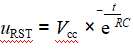

Assuming uRST≥3V can reliably reset the microcontroller, the reset must satisfy

From Equation (2-1), it can be seen that

From Equation (2-2), it is known that the larger the RC, the longer the reset time. If R=1kΩ and C=22μF, then

For a microcontroller with a crystal frequency of 12MHz and a machine cycle of 1μs, a reset time of 11ms meets the requirements.
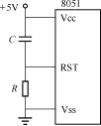
Figure 2-13 Power-on Reset Circuit
(2) Manual Reset
The schematic of the manual reset circuit is shown in Figure 2-14. When the microcontroller is in a “runaway” state (where the microcontroller program enters a dead loop or the microcontroller deviates from user program control), the user can press the button SB to generate a reset signal at the RST pin of the microcontroller, causing it to reset. In Figure 2-14, when the button SB is pressed, the voltage at the RST pin is
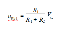
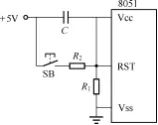
Figure 2-14 Manual Reset Circuit
It should be noted that during manual reset, the voltage uRST must meet the reset requirements, such as uRST≥3V. For example, if R1=1kΩ and R2=200Ω, then
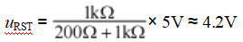
Meets the reset voltage requirements. After releasing the button SB, as the capacitor C charges, uRST will gradually decay and decrease. Comparing Figures 2-13 and 2-14, it can be seen that the manual reset circuit also includes the function of power-on reset, so the manual reset circuit is more commonly used in practical applications.
The circuit shown in Figure 2-15 is a typical minimum system circuit, which includes the most basic hardware conditions necessary for the operation of a microcontroller system, namely power signal, clock circuit, reset circuit, and program memory.
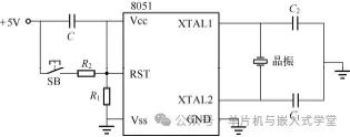
Figure 2-15 Minimum System Circuit

Some Screenshots from Electronic Books