Modbus to MQTT—ADFWEB Gateway Converter–Guangzhou Xinyu IoT
Author:www.adfweb.com.cn Zou Wuyi Mobile185-020-77899 Email: [email protected]
1、Features:
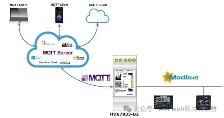
HD67933-B2 is a Modbus master/ MQTT converter with the following features:
– MQTT and Modbus electrical isolation;
– Can be installed on 35mm DIN rail;
– Wide power input range:18…35V DC and 8…24V AC;
– Wide operating temperature range:-40°C to 85°C (-40°F to +185°F).
Configuration:
You need to install Compositor SW67933 software on your computer to perform the following operations:
1. Define MQTT related parameters;
2. Define Modbus line parameters;
3. Specify which Modbus variables need to be sent to the MQTT server;
4. Specify which Modbus variables are written by the MQTT server;
5. Update device configuration.
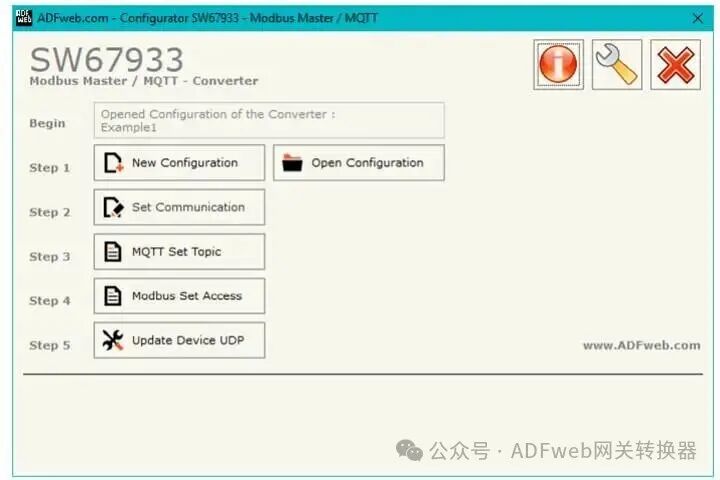
2、“New Configuration” button is used to create a folder containing the entire device configuration.
The device configuration can also be imported or exported:
– To clone the programmable “Modbusmaster/MQTTconverter” configuration for configuring another device in the same way, the folder and all its contents must be retained;
– To clone a project for different versions of that project, simply rename the project folder to another name and use the “Open Configuration” button to open the new folder.
3、Setting Communication:
By clicking the “Set Communication” button in the SW67933 main window (Figure2), the “Set Communication” window (Figure3) will appear.
This window is divided into several sections to define different parameters of the converter:
– Select Device
– Ethernet Connection
– Operating Mode
– Modbus Master
– MQTT
– Ethernet
– TLS (Transport Layer Security)
– NTP (Network Time Protocol)
– Wi-Fi
– GSM / GPRS / LTE
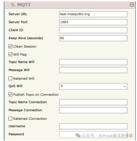
4、This section is used to define the main parameters of the MQTT connection. The meanings of each field are as follows:
– In the “Server URL” field, define the MQTT server’s URL or IP address;
– In the “Server Port” field, define the port used for MQTT communication;
– In the “Client ID” field, define the clientID of the converter (if needed);
– In the “Keep Alive (seconds)” field, define the delay time for sendingKeep Alive messages (in seconds);
– If the “Clean Session” field is checked, the server and client will delete the last MQTT message in the absence ofACK. If this field is not checked, the server and client will retain the last MQTT message and attempt to resend it in case of connection failure or lack ofACK (only applicable forQoS 1 andQoS 2);
– If the “Will Flag” field is checked, the converter will publish a “Will” topic when connecting to the server. With this feature, in case of connection failure, the server will publish this topic to all subscribed MQTT clients;
– In the “Topic Name Will” field, define the topic name for the “Will” message;
– In the “Message Will” field, define the payload of the “Will” message;
– If the “Retained Will” field is checked, the converter will send the “Will” message with the Retain flag enabled. This way, the server will retain the last “Will” message;
– In the “QoS Will” field, define the QoS type of the “Will” message;
– If the “Publish Topic on Connection” field is checked, the converter will publish a topic when connecting to the server;
– In the “Topic Name Connection” field, define the topic name for the connection message;
– In the “Message Connection” field, define the payload of the connection message;
– If the “Retained Connection” field is checked, the converter will send the connection message with the Retain flag enabled. This way, the server will retain the last received connection message;
– In the “Username” field, define the username for connecting to the MQTT server;
– In the “Password” field, define the password required for connecting to the MQTT server.
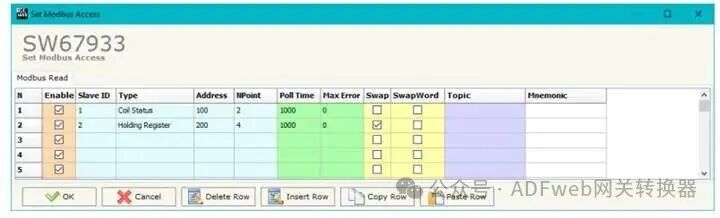
5、MODBUS Set Access Rights (Synchronous Mode):
By clicking the “Modbus Set Access Rights” button in the SW67933 main window (Figure2), the “Set Modbus Access Rights” window will appear.
This section is used to define Modbus read requests.
**MODBUS Read**
The meanings of the fields are as follows:
– If the “Enable” field is checked, Modbus requests are enabled;
– In the “SlaveID” field, define the address of the Modbus device to be read;
– In the “Type” field, define the data type of the registers to be read. You can choose one of the following types:
– Coil Status
– Input Status
– Holding Register
– Input Register
– In the “Address” field, define the starting address of the registers to be read;
– In the “N Points” field, define the number of consecutive registers to be read;
– In the “Polling Time” field, define the delay time for sending requests;
– In the “Max Error Count” field, define the number of consecutive errors after which the converter will pause requests until the next restart. If set to “0”, this feature will be disabled;
– If the “Swap” field is checked, the data in the Modbus registers will be swapped;
– If the “Swap Word” field is checked, the data in the Modbus words will be swapped;
– In the “Mnemonic” field, define the description of the request.