1. Introduction
Modbus, as a widely used general communication protocol, is extensively applied in frequency converters, smart instruments, and various intelligent devices. Previous articles have shared application cases based on the development of custom Modbus communication block instructions, specifically including the communication program implementation between S7-200SMART and Siemens V20 frequency converter, as well as Omron E5EZ instruments.
This article will focus on the method of building the custom Modbus communication block instruction, and at the end, a complete communication block instruction library resource will be provided. Users can simply add this library to the software’s library instruction tab for direct invocation.
2. Custom Modbus Communication Block Instructions
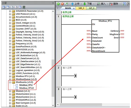
As shown in the figure below, the custom Modbus communication block instruction includes two versions: Modbus_RTU
: suitable for PLC port 0 communication; Modbus_RTU2: used for communication with extended communication signal boards.
3. Building Custom Modbus Communication Block Instructions
(1) Data Buffer Planning Requirements According to the specifications of the MBUS_MSG instruction in the S7-200SMART Modbus master communication library, the data buffer must meet the following requirements:
- Uniform Size: Each message’s data buffer must have the same size.
- Mandatory Parameters: The buffer must include the core parameters of the MBUS_MSG instruction (Slave, RW, Addr, Count).
- Address Offset: The DataPtr of the MBUS_MSG instruction must specify the corresponding address, and the address offset of each message must be consistent with the buffer size.
- (Example: As shown in the figure below, the buffer size for each message is defined as 10 bytes.)
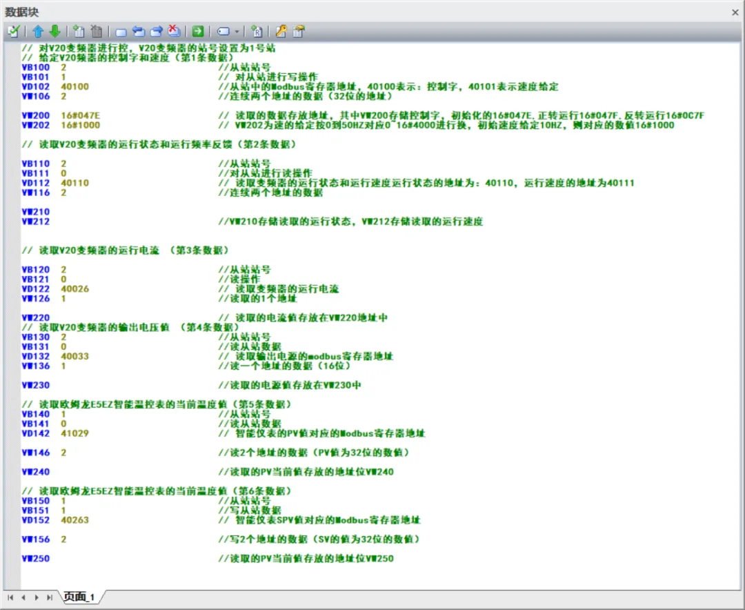
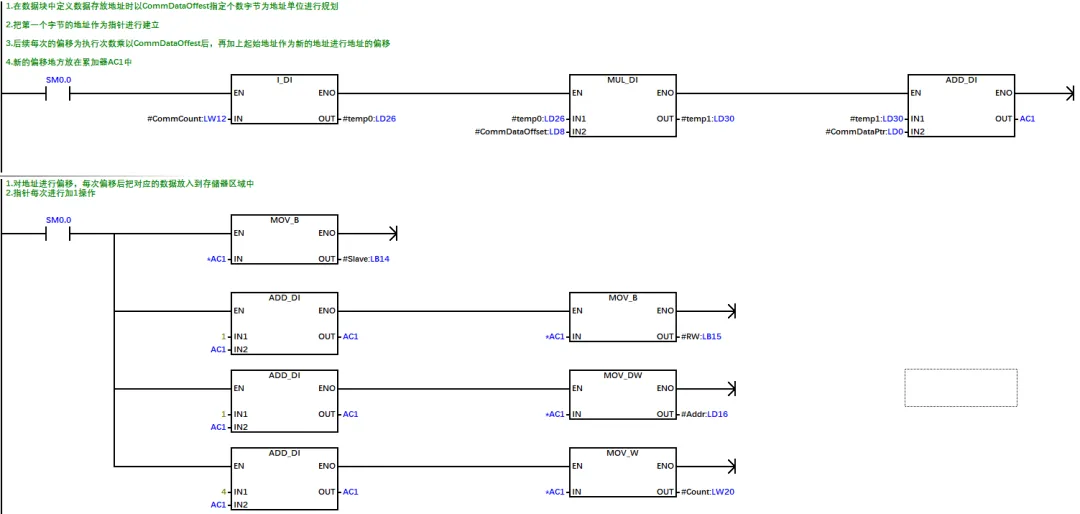
(2) Implementation of Data Processing Subroutine Create a data processing subroutine named “ModbusData” that reads specified data from the preset data buffer using indirect addressing and maps it to the input pins of the MBUS_MSG instruction, thus enabling communication data interaction. The variable definitions for this subroutine are detailed in the variable table shown below.
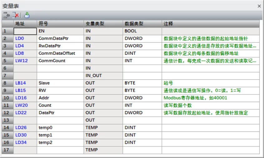
Data Buffer Parameter Description
- CommDataPtr: Specifies the starting address of the data buffer as a pointer. For example, if the first data in the data block starts from address V100, it should be configured as
<span>&VB100</span>. - RwDataPtr: Specifies the storage address for read/write data as a pointer. For example, if the read/write storage area for the first data in the data block is VW200, it should be configured as
<span>&VB200</span>. - CoomDataoffset: Defines the address offset for each data in the buffer. For example, if each data occupies 10 address units, this value should be set to 10.
- CoomCount: Specifies the current data sequence number to be communicated, used to allocate the corresponding numbered data to the MBUS_MSG instruction.
- The output addresses of the above parameters must correspond to the input pins of the MBUS_MSG instruction, and the specific program implementation is detailed in the example below.

(3) Library Instruction Call for Modbus Communication Program Create a new subroutine named “Modbus_RTU” that integrates the following components to achieve communication functionality:
The constructed ModbusData data processing instruction
MBUS_CTRL (control instruction) and MBUS_MSG (message instruction) provided by the Modbus master library
By combining the above instructions, the subroutine for communication functionality can be written. The interface area of this subroutine is defined as follows:
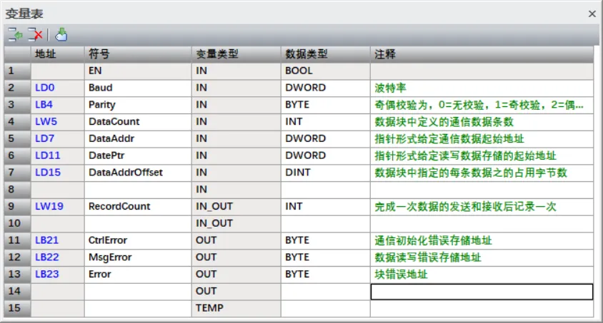
1. Core Parameter Description
- DataCount: Defines the total number of data to be communicated. For example, when planning for 6 data items, this parameter value is set to 6.
- DataAddr: Specifies the starting address of the first communication data as a pointer, bound to the CommDataPtr pin of the ModbusData subroutine (if DataAddr is set to &VB100, then CommDataPtr is also configured to &VB100).
- DataAddPtr: Specifies the starting address for storing read/write data as a pointer, bound to the RwDataPtr pin of the ModbusData subroutine (if DataAddPtr is set to &VB200, then RwDataPtr is also configured to &VB200).
- DataAddrOffset: The address offset in the data buffer, bound to the CoomDataoffset pin of the ModbusData subroutine (if DataAddrOffset is set to 10, then CoomDataoffset is also configured to 10).
- RecordCount: A counter for the number of communication completions, which automatically increments by 1 after each data exchange, bound to the CommCount pin of the ModbusData subroutine, used to allocate the data to be communicated to the MBUS_MSG instruction.
2. Program Execution Logic
- Initialization Operation: First, perform a reset initialization on the system memory to clear the data in the storage area used by the event interval instructions.
- Data Count Verification: Check if the data debugging value is greater than 0:
- Call the Modbus communication initialization instruction to complete the port parameter configuration;
- Call the ModbusData data processing subroutine;
- Allocate the processed data to the MBUS_MSG communication instruction.
- If the debugging value = 0 (no communication data required), the program jumps to label 1 and outputs error code 2 (indicating no current communication data configuration).
- If the debugging value > 0 (communication data exists), execute the subsequent process:
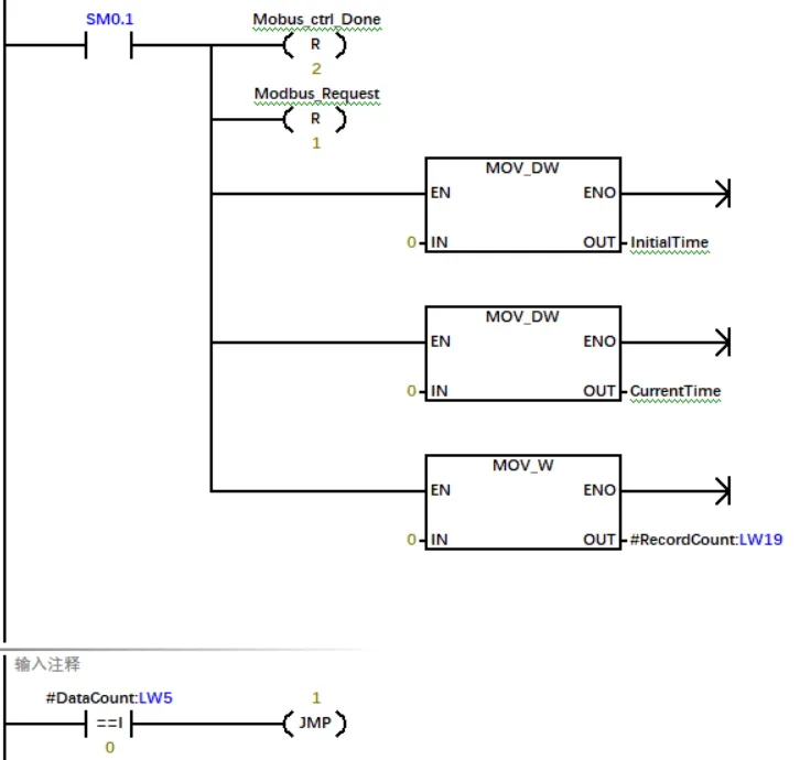
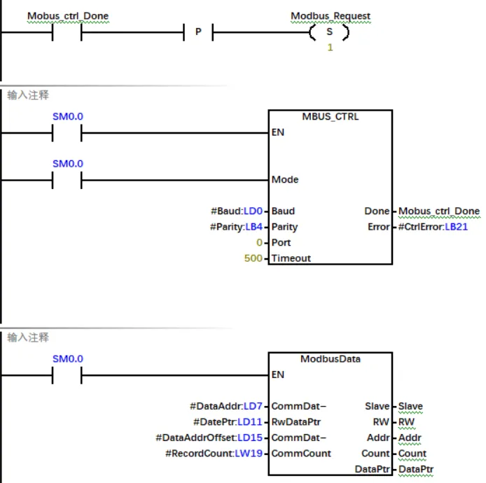
The MBUS_MSG instruction call flow is as follows: After the system completes initialization, it will automatically activate the MBUS_MSG instruction to start the first data exchange. After each data exchange is completed, the RecordCount counter automatically increments by 1, and after an interval of 100ms, the instruction execution is triggered again. When the value of RecordCount is greater than or equal to the preset number of data items DataCount, it indicates that all data has been sent, at which point the system will reset RecordCount to zero and restart the data sending loop.
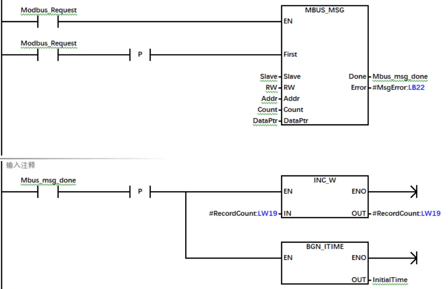
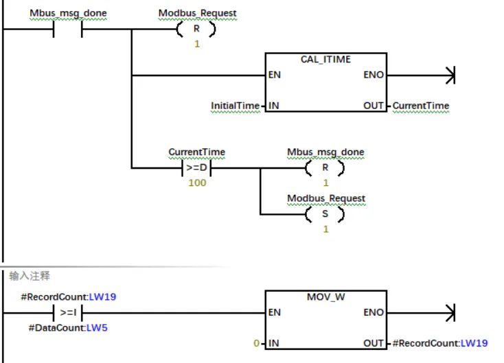
Exception handling mechanism description: After the system initialization is completed, if the activation conditions of the MBUS_MSG instruction cannot be normally connected due to exceptions, the system will automatically start a delay program, forcibly connecting the activation conditions of the instruction after 3 seconds.
Note: In this program, some addresses are defined only by symbolic names without specifying specific addresses. When you encapsulate this program as a library instruction and assign storage addresses to it, the system will automatically allocate actual storage locations for these addresses that only contain symbolic names.
4. Conclusion
The usage instructions for the custom Modbus communication instruction library are as follows:
When actually applying this instruction library to build communication programs, there is no need to master low-level technical knowledge such as subroutine parameter configuration, pointer application principles, and library instruction implementation details. Users only need to understand the data definition rules of the communication data buffer to easily complete the design and application of the Modbus communication program.
If you need to obtain this instruction library, you can scan the QR code below (QR code display omitted here). The library file password is 123456. Interested users are welcome to download and study it themselves, and make personalized modifications and functional optimizations according to actual needs.
The library instructions can recognize the QR code in the figure below, find the 116_S7-200SMARTLibrary file, which contains commonly used library documents, and Modbusrtu is the library instruction established in the example..