1. Basics of Microcontroller Parallel I/O Ports
1. Port Structure:
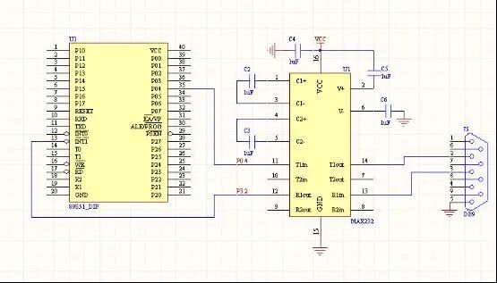
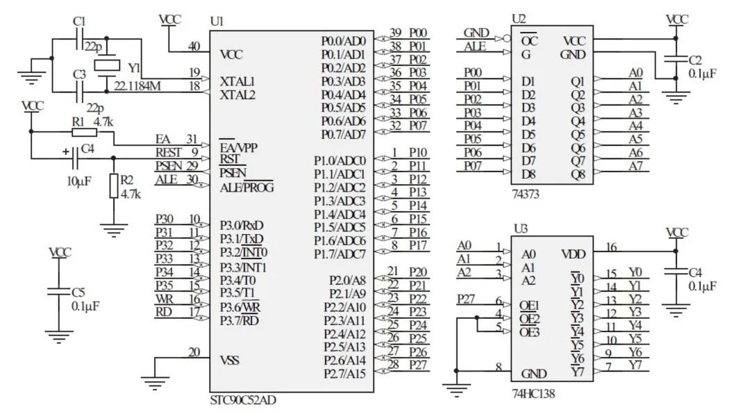
P0 Port: Open-drain structure, requires external pull-up resistor; can be used as data/address bus or general I/O.
P1-P3 Ports: Quasi-bidirectional I/O with internal pull-up resistors, default state is high level.
Driving Capability: P0 port has strong current absorption capability, high level output requires external pull-up; P1-P3 ports can directly drive LEDs (current-limiting resistor required).
2. Operating Modes:
Quasi-bidirectional mode (default): Must write 1 before input, output can be controlled directly.
Push-pull output: High level driven by internal pull-up, enhances output capability (supported by some models).
High impedance state: Used for bus sharing (e.g., when P0 is used as input).
2. Core Points of C51 Programming
1. Keywords and Register Access:
sfr: Define special function registers (e.g., sfr P1 = 0x90;).
sbit: Define bit variables (e.g., sbit LED = P1^0;).
bit type: Declare bit variables (e.g., bit flag;).
2. Delay Function Implementation:
void delay_ms(unsigned int ms) {
unsigned int i, j;
for (i = 0; i < ms; i++)
for (j = 0; j < 120; j++); // 12MHz crystal oscillator approximately 1ms
}
3. Application Examples
1. LED Blinking (P1.0)
#include <reg51.h>
sbit LED = P1^0;
void delay_ms(unsigned int ms) { /* As above */ }
void main() {
while(1) {
LED = 0; // Turn on (low level drive)
delay_ms(500);
LED = 1; // Turn off
delay_ms(500);
}
}
2. Button Control LED (P3.2)
#include <reg51.h>
sbit KEY = P3^2;
sbit LED = P1^0;
void delay_ms(unsigned int ms) { /* Same as above */ }
void main() {
LED = 1; // Initially off
while(1) {
if (KEY == 0) { // Detect button press
delay_ms(10); // Debounce
if (KEY == 0) {
LED = !LED; // Toggle state
while (!KEY); // Wait for release
delay_ms(10);
}
}
}
}
3. Running Light Effect (P1 Port)
#include <reg51.h>
#include <intrins.h> // Include _crol_ shift function
void delay_ms(unsigned int ms) { /* Same as above */ }
void main() {
P1 = 0xFE; // Initial value: 11111110
while(1) {
delay_ms(200);
P1 = _crol_(P1, 1); // Circular left shift
}
}
4. Advanced Application – LCD1602 Driver
#include <reg51.h>
#define LCD_DATA P0 // Data bus
sbit RS = P2^0; // Command/Data selection
sbit RW = P2^1; // Read/Write selection
sbit EN = P2^2; // Enable signal
void LCD_Command(unsigned char cmd) {
RS = 0; RW = 0; // Write command
LCD_DATA = cmd;
EN = 1; // Generate enable pulse
delay_ms(2);
EN = 0;
}
void LCD_Init() {
LCD_Command(0x38); // 8-bit data, two-line display
LCD_Command(0x0C); // Turn on display, turn off cursor
LCD_Command(0x06); // Address increment
}
void main() {
LCD_Init();
LCD_Command(0x80); // First line starting address
// Send display data…
}