The interrupt system and timer/counter of a microcontroller are core modules for implementing real-time tasks and multitasking.
1. Interrupt System
1. Basic Concepts
Interrupt: When a specific event (interrupt source) occurs, the CPU pauses the current task and executes the Interrupt Service Routine (ISR). After completion, it resumes the original task.
Function: Improves CPU efficiency, avoids polling; achieves real-time response.
2. Components of Interrupts
Interrupt Source: Events that trigger interrupts (e.g., timer overflow, external pin signals, serial data arrival).
Interrupt Vector Table: A table that stores the entry addresses of ISRs corresponding to each interrupt source.
Interrupt Priority: Determines the handling order when multiple interrupts are triggered simultaneously (programmable or fixed priority).
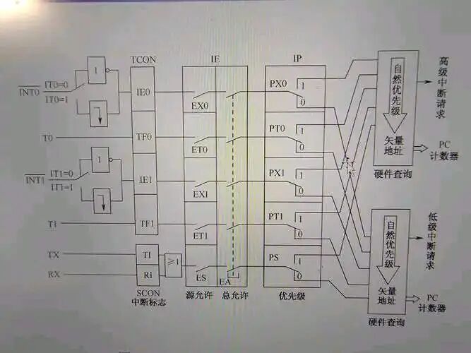
Interrupt Control Register:
Global interrupt enable (e.g., the `EA` bit in the 8051 microcontroller). Individual enable bits for interrupt sources (e.g., `ET0` for Timer 0 interrupt).
Interrupt Flag Bits (e.g., `TF0` indicates Timer 0 overflow, needs to be cleared manually/automatically).
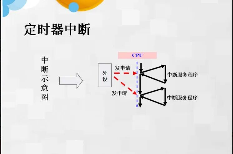
3. Interrupt Handling Process
1. Interrupt Trigger: The interrupt source flag is set to 1.
2. Response Conditions: Global interrupt enable + the specific interrupt source enable.
3. Context Protection: The CPU automatically saves the Program Counter (PC) and Status Register (e.g., PSW).
4. Jump to ISR: Find the ISR entry based on the interrupt vector table.
5. Execute ISR: Handle the interrupt task, need to manually clear the interrupt flag (some microcontrollers clear it automatically).
6. Restore Context: The CPU restores the PC and Status Register, continuing the execution of the original program.
4. Considerations
Interrupt Nesting: High-priority interrupts can interrupt low-priority ISRs (priority configuration is required).
ISR Design: Avoid long blocking operations (e.g., delay functions) to prevent missing other interrupts.
2. Timer/Counter
1. Basic Functions
Timer Mode: Counts internal clock pulses for timing (e.g., generating a 1ms interrupt).
Counter Mode: Counts external pin pulses (e.g., measuring speed, frequency).
2. Core Components
Prescaler: Divides the clock to extend the timing range (e.g., dividing a 12MHz clock by 12 to get a 1MHz counting frequency).
Counter Register (e.g., TH0/TL0): Stores the current count value.
Auto-Reload Register (e.g., ARR): In auto-reload mode, automatically loads the preset value after the counter overflows.
3. Operating Modes
Mode 1 (16-bit Timer): Manual reload of initial value (e.g., in the 8051 microcontroller).
Mode 2 (8-bit Auto-Reload): Suitable for high-frequency timing (e.g., baud rate generation).
Input Capture: Measures the pulse width of external signals.
PWM Output: Generates pulse signals with adjustable duty cycle.
4. Application Scenarios
Periodic Tasks: LED blinking, data sampling.
PWM Control: Motor speed control, LED dimming.
Event Counting: Counting products on a production line.
3. Collaboration between Interrupts and Timer/Counter
Timer Interrupt: Triggered when the timer overflows, executing periodic tasks (e.g., system heartbeat).
Counter Interrupt: Triggered when external events reach a threshold (e.g., over-limit alarm).
4. Common Issues and Solutions
1. Interrupt Not Triggered: Check if the interrupt enable bits and flag bits are cleared.
2. Timing Inaccuracy: Confirm prescaler configuration and initial value calculation; use auto-reload mode to reduce errors.
3. Interrupt Conflicts: Configure priorities reasonably to avoid logical confusion caused by nesting.
4. Resource Contention: When using global variables in ISR, disable interrupts or use atomic operations.
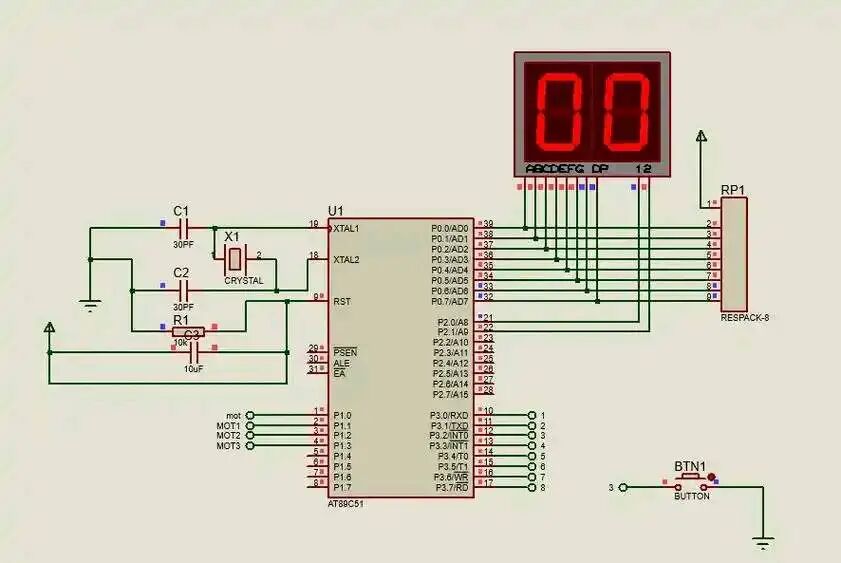
5. Example: Configuration of Timer 0 in the 8051 Microcontroller (Mode 1, 1ms Interrupt)
#include <reg51.h>
void Timer0_Init() {
TMOD |= 0x01; // Timer 0, Mode 1
TH0 = 0xFC; // Initial value high 8 bits
TL0 = 0x18; // Initial value low 8 bits
ET0 = 1; // Enable Timer 0 interrupt
EA = 1; // Global interrupt enable
TR0 = 1; // Start Timer 0
}
void Timer0_ISR() interrupt 1 {
TH0 = 0xFC; // Reload initial value (manual for Mode 1)
TL0 = 0x18;
// User code (e.g., counter accumulation)
}
void main() {
Timer0_Init();
while(1);
}
By deeply understanding the working principles of the interrupt system and timer/counter, developers can efficiently implement real-time control, precise timing, and complex task scheduling, fully utilizing the performance of microcontrollers.