This article introduces the application of Siemens S7-1500 PLC in the control system of spray painting robots and hanging walking mechanisms. It describes the successful implementation of key functions from both hardware and software design perspectives, combined with on-site debugging examples.

1. Project Introduction
In recent years, robotic automated spray painting systems have been widely used in industrial fields such as automotive manufacturing due to their numerous advantages, including high repeatability, good coating quality, reliability, versatility, and high efficiency. However, the manufacturing process of aviation products remains labor-intensive, complex, and harsh, primarily relying on manual manufacturing with a large number of tooling fixtures, resulting in insufficient automation production capacity. Against the backdrop of the national “13th Five-Year Plan” and the vigorous development of intelligent manufacturing in 2025, AVIC Composites Manufacturing Institute has taken the lead in adopting robots for automated production in the spray painting field, accelerating the transformation and upgrading of the enterprise’s production model and enhancing its advanced manufacturing capabilities.
This project employs a movable hanging spray painting 6-axis robot, which is installed on a 3-degree-of-freedom Cartesian coordinate positioning crane. It can perform movements in multiple degrees of freedom (forward and backward, left and right, up and down, and rotation) within the spray booth (dimensions: L30m × W9m × H6.5m). The robot’s arm is equipped with a spray gun, capable of spraying coatings on the surface of large composite material workpieces.
2. Composition of the Hanging Robot Spray Painting System
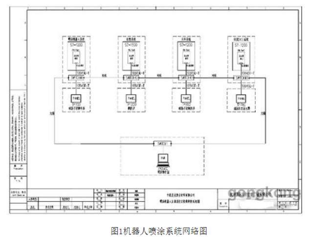
The hanging robot spray painting system consists of a master control system, crane system (hanging walking mechanism), robot system, intelligent paint supply system, and video monitoring system. The system network diagram is shown in Figure 1:
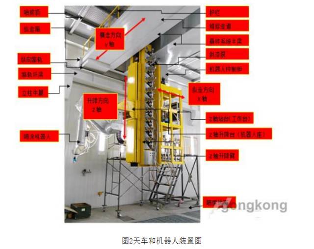
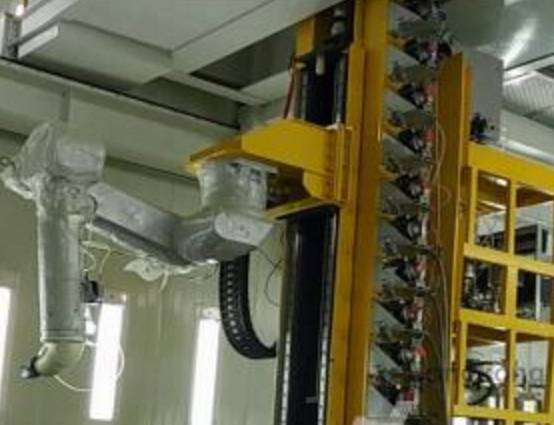
The crane system includes:1 set of longitudinal walking mechanism (X-axis), 1 set of transverse walking mechanism (Y-axis), 1 set of lifting mechanism (Z-axis), and an electrical servo drive system, along with auxiliary facilities such as walkways for maintenance and inspection.As shown in Figure 2:
The intelligent paint supply system consists of a siphon tube, diaphragm pump, material tank, filter, 2KS, pressure regulator, and empty run protector, forming a complete paint supply system, which is an important component of the spray painting system. It plays a crucial role in raw material supply and adjustment of premixed ratios, serving as a necessary prerequisite for the actuator. The materials include paint, hardener, and cleaning agent.
The project selected the Staubli TX250 series 6-axis robot, which is the latest model.
The entire robot system consists of three components: the controller CS8C, the robotic arm, and the manual control pendant (MCP).
3. Control System Architecture
The master control system of this setup uses Siemens S7-1500 PLC as the main controller,
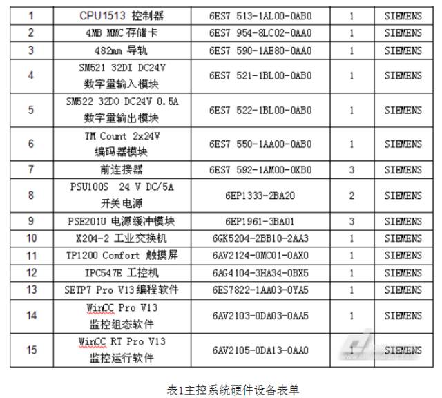
WinCC Professional V13 SP1 as the upper-level operating interface, and TP1200 as the operation panel. The crane, robot, and paint supply systems each use S7-1200 as their controllers. The S7-1500 master control system communicates with the spray painting robot system, paint supply system, and hanging walking system via PROFINET bus, completing overall system control, achieving real-time monitoring and operation of the system’s operational status, and ensuring continuous spraying of the entire workpiece. The control system architecture is shown in Figure 4, and the hardware device list of the main control system is shown in Table 1.

4. Functions Implemented by the Control System
The hanging robot spray painting system can operate the crane system and robot spray painting system independently. On-site, the crane can be operated via the TP700 operation screen, powering on the servo motors for the X, Y, and Z axes, performing zero-point calibration, and absolute positioning.
The on-site screen TP700 of the paint supply system can display the paint level, cleaning agent level, hardener level, pipeline pressure, solenoid valve status, fluid pressure regulator status, automatic mixing conditions of various paints in the 2KS system, pneumatic pump, and empty run protector, etc.
The on-site screen TP700 of the robot system displays the movement status of the six axes: X, Y, Z, RX, RY, and RZ. The on-site teaching pendant can perform offline trajectory planning for the robot.
The master control system includes both on-site control and remote control systems.The on-site control system can communicate with the robot system, hanging walking system, and paint supply system via the bus, completing overall system control for continuous spraying of the entire workpiece; the remote control system primarily achieves real-time monitoring and operation of the system’s operational status.
The master control system can control and display the status of subsystems. It can automatically perform color changes, material additions, and cleaning operations for the paint supply system. It can also correct errors generated during the movement of the hanging walking mechanism.
5. Technical Points of the Spray Painting Process Flow and Control
The spray painting process flow of the hanging robot spray painting system is as follows:
First, the crane system, paint supply system, and spray painting system are prepared, the workpiece enters the designated position and is positioned → the system detects the actual position of the workpiece → coordinate fitting → teaching (manual debugging program) → start operation, the master control reads the spray painting “workpiece data”, sends the spray painting “trajectory number” and spray painting “formula confirmation” signal to the robot spray painting system → the robot spray painting system reads the spray painting “trajectory number” and color “formula number” → if the robot spray painting system confirms the current spray painting formula, it sends a “spray request” signal for position 1 to the master control → after the three axes of the hanging system reach the designated position 1, it sends a “crane has reached the spray position” signal to the master control → 2KS mixing, the robot begins automatic spraying (calling spray program 1) → spray painting workpiece area 1, spraying completed, the robot returns to the HOME position and stops, sending a “spray completed” signal to the master control → the master control reads the “spray completed” signal, changes the workpiece pointer to point to workpiece data for area 2, sends the spray painting “trajectory number” and spray painting “formula confirmation” signal to the robot spray painting system → the robot spray painting system reads the spray painting “trajectory number” and color “formula number” → if the robot spray painting system confirms the current spray painting formula, it sends a “spray request” signal for position 2 to the master control → after the three axes of the hanging system reach the designated position 2, it sends a “crane has reached the spray position” signal to the master control → 2KS mixing, the robot begins automatic spraying (calling spray program 2) → spray painting workpiece area 2, spraying completed, the robot returns to the HOME position and stops…
Following the above procedure, spray painting workpiece area 3, area 4… area n, until all spray painting tasks for the workpiece are completed → the robot returns to the zero position (HOME point), and the crane returns to the original position, and the workpiece is taken offline.

To achieve continuous spraying of the entire workpiece until the crane returns to the original position, the master control’s S7-1500 controller serves as the most critical core component of the entire system, coordinating the work of the crane and robot systems. When manually teaching and debugging the robot program, the X, Y, Z coordinate values of the crane for each area of the workpiece and the robot’s trajectory number must be manually recorded. By inputting this data on the master control’s operation screen TP1200 or on the central control’s industrial computer, it is stored in the data block of the master control S7-1500 PLC. During automatic operation, the system will automatically call the stored data step by step according to the process sequence.
Due to the variety of workpiece types, the sizes of the areas defined for different workpieces vary, and each area consists of multiple values. The data block for storing data is nested, meaning it is a multi-dimensional array, so the size of the data block must be sufficiently large to meet production requirements. If the master control chooses to use the ordinary S7-300/400 PLC with STEP7 programming to implement data storage and retrieval, it would face certain difficulties. Therefore, the S7-1500 PLC is selected to use TIA Portal’s SCL programming method to achieve this functionality, which is more convenient and easier. The following describes the implementation process.
Process of Establishing the Workpiece Process Data Table:
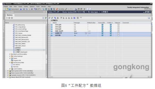
1. In TIA Portal V13 SP1 programming software, add a new “PLC data types” (equivalent to user-defined DB blocks established in Step7), named “Workpiece Formula”, and add “Crane X Coordinate” (defined as integer data type), “Crane Y Coordinate” (defined as integer data type), “Crane Z Coordinate” (defined as integer data type), and “Robot Trajectory Number” (defined as byte data type), along with two spare data points to prevent future customer requests for new functions, namely “Paint Formula Number” (defined as Word data type) and “Paint Flow” (defined as integer data type). Currently, these two data points are directly input on the screen for the paint supply system to receive.
2. In the program files of TIA Portal, add a global type DB block, data number 8, named “Workpiece Process Table 1”, open this data block, and add a name called “Workpiece Data”, with the data type being the array “Workpiece Formula” established above, with a range of 1 to 200, as shown in Figure 9. After expanding the data group, it is shown in Figure 10. Also, check the “Retain” option for power-off retention.
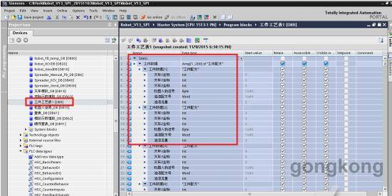
Figure 9 Establishment of “Workpiece Process Table 1” Data Group
Figure 10 Expansion of “Workpiece Process Table 1” Data Group
3. Actual Teaching Fill-in SCL Program Writing: In the program files of TIA Portal, add function block FB63, define input and output interfaces, including X-axis position, Y-axis position, Z-axis position, robot path number, paint number, maximum workpiece number, HMI storage confirmation, counting pointer, and other parameters. The interface parameters are shown in Figure 11:
FB63 Main Program Writing is as follows:
IF #HMI Confirmation Pulse = 1 AND #Counting Pointer <= #Maximum Workpiece Number THEN
// Input values from the touch screen into the DB Workpiece Process Table
“Workpiece Process Table 1”.Workpiece Data[#Counting Pointer].Crane X Coordinate := #X Axis Position;
“Workpiece Process Table 1”.Workpiece Data[#Counting Pointer].Crane Z Coordinate := #Z Axis Position;
“Workpiece Process Table 1”.Workpiece Data[#Counting Pointer].Robot Trajectory Number := #Robot Path Number;
“Workpiece Process Table 1”.Workpiece Data[#Counting Pointer].Paint Formula Number := #Paint Number;
#Counting Pointer := #Counting Pointer + 1;
// After inputting an array, increment the pointer to point to the next position
END_IF;
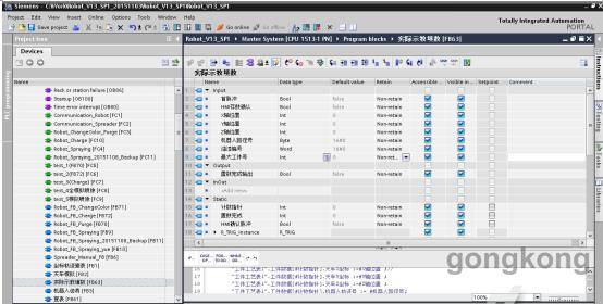
Figure 11 Actual Teaching Fill-in Interface Parameters
Below is the teaching data table for one of the large wings, requiring 17 fixed-point sprayings to complete the spraying of the entire part.
Serial Number X-axis Coordinate Value Y-axis Coordinate Value Z-axis Coordinate Value Robot Trajectory Number
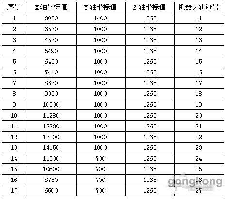
Note: The units for X/Y/Z are mm
Table 2 Large Wing Teaching Data Table
Automatic Reading of Multi-dimensional Arrays Process:This process is relatively complex, involving reading each group of data stored in the “Workpiece Process Table 1” array DB8, then transmitting the X-axis position, Y-axis position, and Z-axis position to the crane system’s S7-1200 PLC via PROFINET communication, and transmitting the robot trajectory number to the robot system’s S7-1200 PLC via PROFINET communication. This follows the sequence of the spray painting process of the hanging robot spray painting system.
Automatic Reading of Workpiece Process Table SCL Program Writing: In the program files of TIA Portal, add function block FB91, define input and output interfaces. The interface parameters are shown in Figure 12:

Figure 12 Automatic Reading of Workpiece Process Table Interface Parameters
FB91 Partial Program Writing is as follows:
IF #Start Signal Pulse = 1 AND First Step = 0 THEN
#o Crane X Coordinate := “Workpiece Process Table 1”.Workpiece Data[#i Designated Start Step].Crane X Coordinate;
#o Crane Y Coordinate := “Workpiece Process Table 1”.Workpiece Data[#i Designated Start Step].Crane Y Coordinate;
#o Crane Z Coordinate := “Workpiece Process Table 1”.Workpiece Data[#i Designated Start Step].Crane Z Coordinate;
#o Robot Trajectory Number := “Workpiece Process Table 1”.Workpiece Data[#i Designated Start Step].Robot Trajectory Number;
#o Paint Formula Number := “Workpiece Process Table 1”.Workpiece Data[#i Designated Start Step].Paint Formula Number;
#i Designated Start Step := 1;
#Counting Pointer := #i Designated Start Step;
#o Check Table Completion Crane Return to Origin := 0;
END_IF;
6. Conclusion
This project utilizes Siemens S7-1500 PLC and TIA Portal software, with S7-SCL language extensively applied during programming. Compared to other types of programming languages for Siemens PLCs, SCL has significant advantages in processing multi-dimensional array data, making control tasks that require repetitive use more convenient. Not only is the program size smaller, but it is also less prone to errors, significantly shortening the debugging cycle. Overall, the adoption of the S7-1500 series PLC in the project development process has shortened the design and debugging cycles, improved the methods and efficiency of equipment debugging, and is a powerful tool for industrial equipment research and development.
Since the system was put into operation, the equipment has been running well, with reliable and stable control, shortening the spray operation cycle, improving production efficiency, and achieving ideal results in coating thickness and uniformity. It has greatly reduced the labor intensity of workers and improved the working environment, gaining recognition from the leaders and frontline employees of the composite materials department. This has realized the leap from traditional manual spray operations to efficient, intelligent, and precise automated spray operations in aircraft manufacturing, meeting the performance indicators of the entire aircraft, improving product quality, enhancing the rapid development and production capabilities of the new generation of aircraft, and strengthening the core competitiveness of the aviation industry.
Disclaimer: This article is a network reprint or adaptation, and the copyright belongs to the original author. If there are any copyright issues, please contact for deletion!