Concepts, Production, and Applications of DAC and TCG Curves
1 DAC/TCG Options
1.1 Concepts of DAC and TCG Curves
1.1.1 Definition and Function of DAC Curve
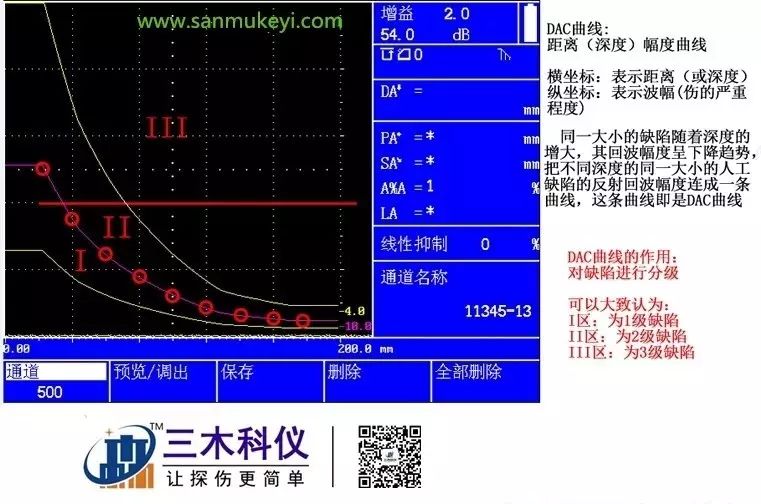
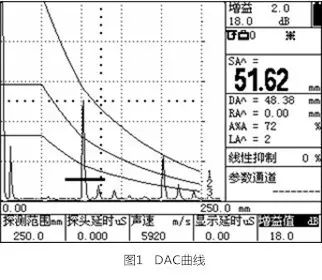 Definition of DAC: DAC is a distance-amplitude curve. For the same equivalent defect, as the depth increases, the echo amplitude decreases exponentially due to signal attenuation, beam spreading, and other factors. The echo amplitudes of the same equivalent artificial defects at different depths form a curve known as the DAC curve.
Function of DAC: The DAC curve is used to distinguish the amplitude variations of reflectors of the same size but at different distances. Typically, after the DAC curve is plotted, regardless of the position of the reflectors in the material, the echo peaks produced by reflectors of the same size will lie on the same curve. Conversely, reflectors that are smaller than the size indicated by the curve will have echoes below the curve, while larger ones will have echoes above the curve.
1.1.2 Definition and Function of TCG Curve
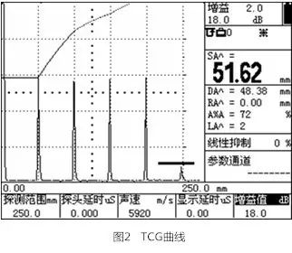 Definition of TCG: The TCG curve is a depth compensation curve, compensating for the amplitude of echo reflections at different depths based on the downward trend of the DAC curve along the depth direction, forming a curve known as the TCG curve.
Function of TCG: The TCG function compensates for the amplitude of echoes from reflectors of the same size regardless of their depth in the tested material. Therefore, in TCG mode, when the gain conditions of the flaw detector remain unchanged, it is more beneficial to detect defects located deeper within the material. After activating DAC/TCG, a symbol will be displayed in the indicator symbol column.
1.2 Production and Setting of DAC/TCG Curves
Note: 1. Before recording reference points, the calibration of the flaw detector and probe, as well as necessary settings (transmit/receive, parameters, etc.), must be completed.
2. This instrument can record up to 16 points, and 2 points can automatically generate the DAC curve; it is recommended to record at least 3 points.
3. After recording reference points, to ensure measurement accuracy (according to international practices for flaw detectors), these settings will not be allowed to be modified.
1.2.1 Steps to Produce DAC Curve
The DAC curve represents the echo amplitudes of reflectors of the same size at different depths. The flaw detector uses the recorded reference points to establish the DAC curve, and the steps to produce the DAC curve are as follows:
Step 1: Press the [DAC] key to open the DAC menu.
Step 2: Place the probe near the first reflection hole and move the probe to obtain the highest reflected echo. If necessary, adjust the gain to bring the echo peak close to 80% of full screen, but the highest echo must not exceed full screen height. Adjust the A gate starting point to encompass this echo.
Important Note: Press the [Peak Memory] key to activate the peak memory function to conveniently find and record the peak information of the highest echo.
Step 3: Position the A gate over the first reference echo and stabilize the echo, then press the [F3] key under the calibration point function item to select this function, and press the [F3] key again; the calibration point will change from 0 to 1, indicating that the highest point of the echo has been recorded.
Step 4: Repeat the methods of steps 2 and 3 to record more echo peaks. When two calibration points are recorded, the DAC curve is automatically generated.
1.2.2 Deleting Calibration Points
If you need to delete a calibration point, press the [F4] key under the delete calibration point function item to execute the deletion.
Note: The delete calibration point function deletes the calibration point at the maximum distance (i.e., the calibration point on the far right of the screen is deleted first), which may not be the last calibrated point. Therefore, it is recommended that users record and delete in order of distance (first record echoes from shallower reflection holes, then from deeper ones).
1.2.3 Recalibrating a Calibration Point
If the user only wants to adjust or recalibrate the amplitude of a specific calibration point, they can use the edit calibration point function on the second page.
The steps are:
Press the [F5] key to enter the second page, press the [F2] key to select edit calibration point, and continue pressing the [F2] key; this parameter will change from off to on, while the first calibration point will be displayed with a symbol “*” in the echo area.
Continue pressing the [F2] key to switch to the next calibration point until the parameter changes back to off.
Repeat this process. Once the desired calibration point is selected, press the [F3] key to select adjust, and rotate the parameter adjustment knob to adjust the height of the amplitude curve for this test point.
Recalibration
If you need to recalibrate this calibration point, press the [F4] key to select recalibrate, stabilize the echo, and press the [F4] key once more for recalibration.
Note: Once two calibration points are correctly completed, the DAC curve will be automatically plotted on the screen.
1.2.4 Generating TCG Curve
If the flaw detector needs to operate in TCG mode, modify the DAC/TCG function item by pressing [F1] under DAC/TCG to switch to TCG, then press the [F5] key to enter the fourth page, and modify the evaluation curve to the baseline; the TCG will then be displayed on the screen.
1.2.5 Setting DAC Offset Curve
Press the [DAC] key, then press the [F5] key to enter the third page.
Press the [F2] key to select the “Evaluation Line” menu, and rotate the knob to adjust the offset value of the evaluation line.
Press the [F3] key to select the “Quantitative Line” menu, and rotate the knob to adjust the offset value of the quantitative line.
Press the [F4] key to select the “Disposal Line” menu, and rotate the knob to adjust the offset value of the disposal line.
Once the offset curve settings are complete, they will be displayed on the screen, and the name of the offset curve will be indicated behind the curve, where:
EL: Evaluation Line
SL: Quantitative Line
RL: Disposal Line
GL: Baseline
1.2.6 Setting Curve Compensation Values
Press the [DAC] key, then continuously press the [F5] key to enter the fourth page.
Select the surface compensation function item, rotate the knob to adjust and set the workpiece surface compensation value (only valid in DAC mode).
Select the attenuation function item, rotate the knob to adjust and set the material attenuation compensation value (only valid in TCG mode);
Note:
1. The workpiece surface compensation value is used to compensate for the differences caused by the coupling conditions between the calibration block and the surface of the material being tested.
2. The material attenuation compensation value is used to compensate for the differences caused by the different sound attenuation coefficients between the calibration block and the material being tested;
3. The DAC/TCG reference points, curve offsets, and compensations, along with the DAC mode (off, TCG, DAC) can be stored in the channel file along with other parameters for future retrieval.
1.3 DAC Equivalent Calculation
In DAC mode, the DAC offset curve divides the screen echo display area into several regions. For example, the three DAC offset curves shown in Figure 7-1 divide the screen into four regions: the topmost offset curve is called the disposal line, the middle offset curve is called the quantitative line, and the bottom offset curve is called the evaluation line. To utilize the DAC curve, the following steps must be performed:
Step 1: After entering the DAC menu, select the DAC/TCG function item, rotate the knob or continuously press the corresponding [F1] key to adjust the function item content until it displays DAC.
Step 2: Select the display of DAC equivalent calculation results:
Press the [F5] key to enter the third page, select the equivalent standard function item, and rotate the knob or continuously press the corresponding [F5] key to select the DAC offset curve used for measurement; the selected curve will be displayed in color.
Step 3: Adjust the display reading, setting the measurement result DACr to the current display;
Step 4: Move the A gate to encompass the A scan echo being measured, and the dB equivalent difference between the amplitude of the reflector echo and the height of the DAC offset curve will be calculated and displayed.
Click the lower left corner “Read Original” to enter the official website of Sanmu Technology to check details!