

《Statistics of All Polyester (PET) Production Enterprises Nationwide《Statistics of 50 Coal-to-Hydrogen Enterprises Nationwide》Statistics of All Methanol Production Enterprises Nationwide《Modern Coal Chemical Industry Series Research Report 2019 Edition——Coal-to-Olefins+Coal-to-Ethylene Glycol+Coal-to-Ethanol+Coal-to-Oil+Coal-to-Natural Gas Compilation and Interpretation of Modern Coal Chemical Policies《Compilation of Polyolefin Technology in China》《Urea Market Research Report》,《China Coal Chemical Strategic Planning Report–Shanxi Chapter、Inner Mongolia Chapter ,Shanxi Chapter,Contact WeChat: 3181066003, please indicate the report when adding(Click on the blue text to learn more)
Among the many solutions for medium and long-distance communication between MCUs, RS-485 is widely used in factory automation, industrial control, community monitoring, and water resource automatic measurement due to its simple hardware design, easy control, and low cost.
However, RS-485 bus still has defects in anti-interference, adaptability, and communication efficiency. Improper handling of some details often leads to communication failures or even system crashes, making it crucial to improve the operational reliability of the RS-485 bus.
1. Hardware Design of RS-485 Interface Circuit
There are two methods for bus matching. One is to add matching resistors. A 120Ω matching resistor should be connected between the differential ports at both ends of the bus,VA and VB, to reduce reflections and absorbed noise caused by mismatching, effectively suppressing noise interference.However, matching resistors consume a large current, making them unsuitable for systems with strict power consumption limits.
The other more energy-efficient matching scheme is RC matching, which uses a capacitor C to block the DC component, saving most of the power. However, selecting the value of capacitor C is challenging, requiring a compromise between power consumption and matching quality. Besides these two methods, there is also a matching scheme using diodes. Although this scheme does not achieve true matching, it leverages the clamping effect of diodes to quickly weaken reflected signals, thereby improving signal quality and achieving significant energy savings.
2. Pull-up Resistors for RO and DI Terminals
Asynchronous communication data is transmitted in bytes. Before each byte transmission, a low-level start bit is used for handshaking. To prevent interference signals from inadvertently triggering RO (receiver output) to produce negative transitions, which would cause the receiving MCU to enter the receiving state, it is recommended to connect a 10kΩ pull-up resistor to RO.
3. Ensure RS-485 Chip is in Receive Input State at Power On
It is recommended to use an inverter to control the transceiver control terminal TC via an MCU pin, rather than controlling it directly with the MCU pin to avoid interference with the bus when the MCU powers on.
RS-485 bus is a two-wire interface in parallel connection. If one chip fails, it may cause the bus to be “pulled dead.” Therefore, isolation should be added between the two wires VA and VB and the bus. Usually, a 4-10Ω PTC resistor is connected in series between VA, VB, and the bus, along with a 5V TVS diode to eliminate line surge interference. If PTC resistors and TVS diodes are not available, ordinary resistors and voltage regulators can be used instead.
5. Reasonable Chip Selection
For external devices, to prevent strong electromagnetic (lightning) impacts, it is recommended to select TI’s 75LBC184 and other lightning protection chips. For applications requiring many nodes, consider using SIPEX’s SP485R.
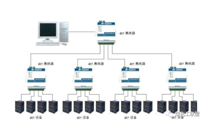
2. RS-485 Network Configuration
The number of network nodes is related to the driving capability of the selected RS-485 chip and the input impedance of the receiver. For example, the nominal maximum value of 75LBC184 is 64 nodes, while SP485R’s nominal maximum is 400 nodes. In practice, due to cable length, wire diameter, network distribution, and transmission rate differences, the actual node count often does not reach theoretical values. For instance, when using 75LBC184 in an RS-485 network distributed over 500m, if the number of nodes exceeds 50 or the rate exceeds 9.6kb/s, the operating reliability significantly decreases. It is generally recommended to select the number of nodes at 70% of the maximum value of the RS-485 chip, with transmission rates between 1200-9600b/s. For communication distances within 1km, considering communication efficiency, node count, and distance, 4800b/s is optimal. For distances over 1km, methods such as adding relay modules or reducing rates should be considered to improve data transmission reliability.
2. Distance Between Nodes and Backbone
Theoretically, the shorter the distance between RS-485 nodes and the backbone (T-head, also called lead wire), the better. Nodes with T-heads less than 10m can use T-type connections without significant impact on network matching, but for very small node spacing (less than 1m, such as LED module screens), star connections should be used. If T-type or bead-type connections are used, they may not work properly. RS-485 is a half-duplex structured communication bus, mostly used in one-to-many communication systems, so the host (PC) should be at one end, not in the middle forming a T-type distribution of the backbone.
3. Improving RS-485 Communication Efficiency
RS-485 is usually applied in one-to-many master-slave response communication systems, and compared to RS-232 and other full-duplex buses, its efficiency is significantly lower, so selecting suitable communication protocols and control methods is very important.
1. Bus Steady-State Control (Handshake Signal): Most users choose to set the transceiver control terminal TC to high level 1ms before data transmission, allowing the bus to enter a stable sending state before sending data; after data transmission is complete, TC is set to low level after a 1ms delay, ensuring reliable sending is complete before entering the receiving state. The delay at the TC terminal has satisfied the requirement of four machine cycles.
2. To ensure data transmission quality, while verifying each byte, it is important to minimize the characteristic word and check word. The commonly used data packet format consists of a header code, length code, address code, command code, data, check code, and tail code, with each data packet length reaching 20-30 bytes. In the RS-485 system, such protocols are not very concise. Users are recommended to use the MODBUS protocol, which has been widely applied in international standards for equipment and systems in industries such as water resources, hydrology, and electricity.
4. Power Supply and Grounding of RS-485 Interface Circuit
For measurement and control networks built by combining MCU and RS-485 microsystems, it is preferable to adopt independent power supply schemes for each microsystem. It is best not to use a single large power supply to provide parallel power to the microsystems, and the power lines (AC and DC) should not share the same multi-core cable with the RS-485 signal lines. RS-485 signal lines should preferably be twisted pairs with a cross-sectional area greater than 0.75 square millimeters, rather than flat lines. For each small-capacity DC power supply, using a linear power supply LM7805 is more suitable than using a switching power supply.
Of course, attention should be paid to the protection of LM7805:
1. Connect a 220-1000μF electrolytic capacitor between the input terminal of LM7805 and ground;
2. Connect a 1N4007 diode in reverse between the input and output terminals of LM7805;
3. Connect a 470-1000μF electrolytic capacitor and a 104pF ceramic capacitor in reverse between the output terminal of LM7805 and ground, along with a 1N4007 diode in reverse;
4. The input voltage should be optimal at 8-10V, with a maximum allowable range of 6.5-24V. TI’s PT5100 can be used to replace LM7805 to achieve an ultra-wide voltage input of 9-38V.
In some industrial control fields, due to the complexity of the site, there exists a high common-mode voltage between various nodes. Although the RS-485 interface uses differential transmission, providing some resistance to common-mode interference, when the common-mode voltage exceeds the limit receiving voltage of the RS-485 receiver, i.e., greater than +12V or less than -7V, the receiver will no longer operate correctly, and in severe cases, it may even burn out the chip and equipment.
The solution to this problem is to isolate the system power supply and the RS-485 transceiver power supply through DC-DC; isolate the signal through optical isolation to completely eliminate the impact of common-mode voltage. The ways to implement this solution can be divided into:
1. Constructing a circuit with optocouplers, isolated DC-DC, and RS-485 chips;
2. Using secondary integrated chips, such as PS1480, MAX1480, etc.
6. Common Faults and Handling Methods in RS-485 Systems
RS-485 is a low-cost, easy-to-operate communication system, but it has weak stability and strong interdependence. Usually, if one node fails, it can lead to the overall or partial paralysis of the system, and it is often difficult to diagnose. Therefore, we introduce some common methods for maintaining RS-485.
1. If the system is completely paralyzed, it is mostly due to the breakdown of the VA and VB of a node chip to the power supply, using a multimeter to measure the differential voltage between VA and VB to be zero, while the common-mode voltage to ground is greater than 3V. At this time, the common-mode voltage size can be used for troubleshooting; the larger the common-mode voltage, the closer to the fault point, and vice versa;
2. If several consecutive nodes on the bus cannot work normally, it is generally caused by a fault in one of the nodes. A fault in one node can cause 2-3 adjacent nodes (generally subsequent ones) to be unable to communicate. Therefore, disconnect them one by one from the bus. If the bus can recover normally after disconnecting a certain node, that node is faulty;
3. In RS-485 systems with centralized power supply, it often happens that some nodes do not function normally when powered on, but it is not always the same. This is due to unreasonable design of the RS-485 transceiver control terminal TC, causing the nodes to be in a confused sending and receiving state during power-on, resulting in bus congestion. The improvement method is to install power switches for each microsystem and power them on separately;
4. If the system is basically normal but occasionally experiences communication failures, it is generally due to unreasonable network construction leading to the system’s reliability being in a critical state. It is best to change the wiring or add relay modules. One emergency method is to replace the failing node with a higher-performance chip;
5. If the TC terminal is in a long sending state due to MCU failure, causing the bus to be pulled dead, readers are reminded not to forget to check the TC terminal. Although RS-485 specifies that a differential voltage greater than 200mV can work normally, actual measurements show that in a well-functioning system, the differential voltage is generally around 1.2V (due to differences in network distribution and transmission rates, it may vary between 0.8-1.5V).
In the following titles, you can read more exciting articles
-
22-Year-Old Young Town Chief Angrily Hits County Chief for Public Interest
-
In-Depth: This is a Deformed Era of Infidelity!
-
Actually, the Most Terrifying is Not the Evil Spirits, But…
-
China’s Last Coroner Unveils the Most Bizarre and Disturbing Cases, Caution Advised
