This article includes how to use jumpers for repairs/modifications on printed circuit boards and electronic components to achieve electrical connectivity between two points. The article aims to lay the foundation for adding jumpers during the repair/modification process.
Tools, materials, and supplies:
PCB support
Cleaner
Precision tool set
Soldering iron
Wiping cloth
Wire
Wire points
Wire stripper
General Rules
- Unless otherwise specified, jumpers should be placed on the component side of the component or printed board.
- Jumpers should be routed as straight as possible in an XY manner, minimizing bends. (See Figure 1)
- The height of the jumper must not exceed 3.2 mm (0.125 inches) above the surface of the circuit board or the components or leads to avoid interference with the installation of the circuit board.
- Do not use bare conductor jumpers longer than 12.7 mm (0.50 inches). Bare conductor jumpers shorter than 12.7 mm (0.50 inches) must not violate minimum electrical clearance requirements.Note: The 12.7 mm (0.50 inches) dimension refers to the length between terminations.
- Jumpers can cross connection pads, but sufficient space must be left to move the jumper away from the connection pad for component replacement. Jumpers must not cross pads or vias used as test points.
- Jumpers must not pass under or over component leads or the body of the component. Contact with heat sinks must be avoided.
- Jumpers must not pass through component packages unless the component layout prohibits routing in other areas.
- Jumpers should have stress relief functionality.
- Jumpers can pass through plated holes as long as the wire is insulated and the hole is fitted with an insulating sleeve. If drilling is required, use the following method. (See Figure 2)A. Drill a hole that is 0.25 mm (0.010 inches) larger than the diameter of the insulation. B. Check for burrs or exposed internal circuits in the hole. C. Record the new hole on the control chart.Note: Be careful not to disturb surface and internal conductors when drilling.
- Jumpers soldered into plated through holes must be clearly visible on the other side.
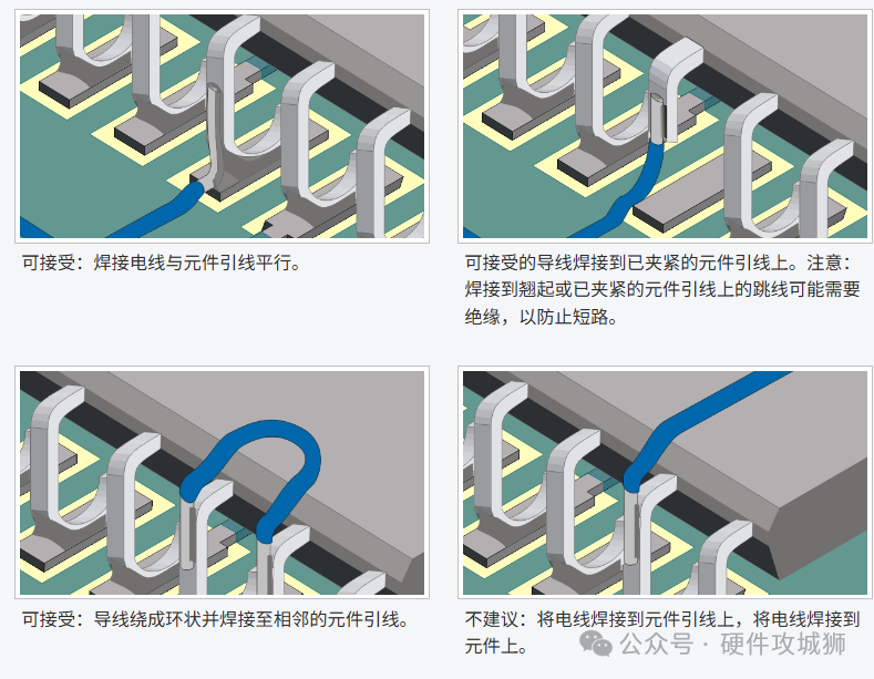
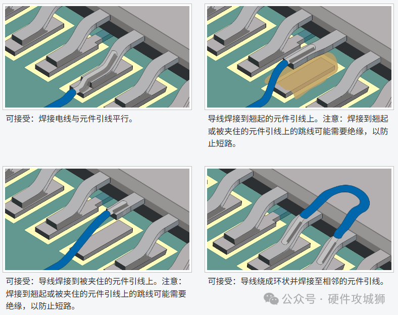
- Jumpers soldered to lifted or trapped component leads may require insulation to prevent short circuits. (See Figure 3)
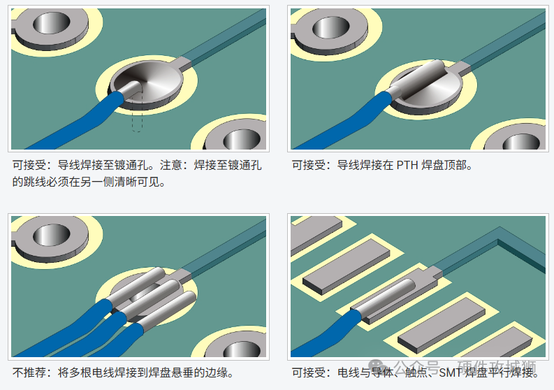
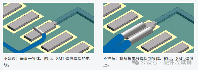
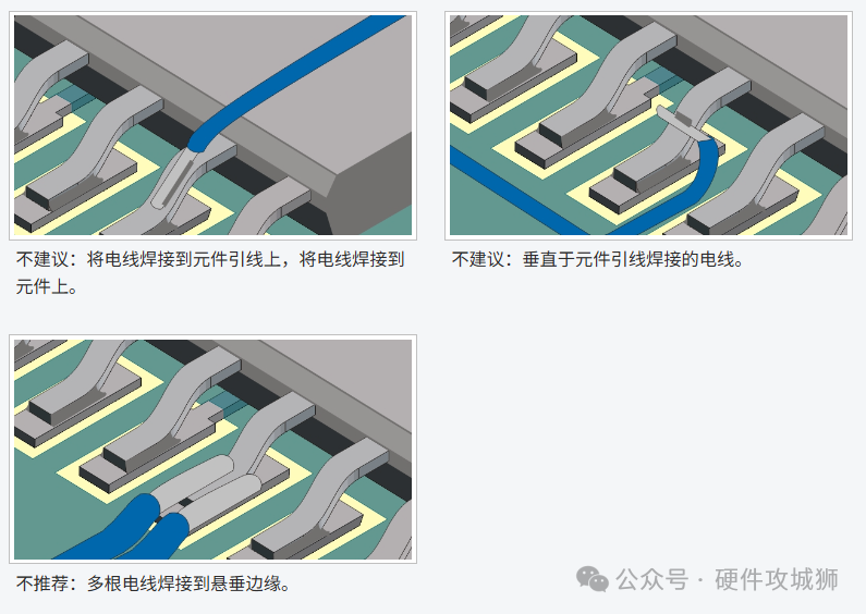
- Jumpers can be terminated in various ways. See the illustrations.
PCB Preparation
- Clean the area.Note: Cleaning is usually more difficult if wires are already in place.
- Remove coatings or oxides from the ends of the leads, pads, or wires to be soldered as needed. Clean the area.
- If necessary, remove solder from the connection points. Clean the area.
- Measure the approximate length of each wire needed.
Jumper Selection
- Do not use bare conductor jumpers longer than 12.7 mm (0.50 inches). Bare conductor jumpers shorter than 12.7 mm (0.50 inches) must not violate minimum electrical clearance requirements.Note: The 12.7 mm (0.50 inches) dimension refers to the length between terminations.
- Do not use silver-plated wire; corrosion may occur in some cases.
- Choose wire with the minimum diameter that can carry the required current.
- The insulation requirements of the wire should withstand soldering temperatures, have some abrasion resistance, and have a dielectric strength equal to or greater than that of the circuit board insulation material.
- It is recommended to use solid insulated copper wire, tin-lead plated, 22 to 32 AWG, with insulation materials such as Kynar, Milene, Kapton, Teflon, or equivalent.Note: Do not use wire with notches or damage to the conductor.
Jumper Preparation
- Cut the jumper to be approximately 12.7 mm (0.50 inches) longer than the expected required length.Note: The length and specifications of the jumper can be critical. All wires will have resistance (impedance) to current. This impedance is crucial for electronic circuits. Be sure to refer to the wiring list for specific jumper requirements.
- Strip the insulation from both ends of the jumper.Note: The stripping length depends on the termination method.
- If necessary, tin the stripped ends with solder. Clean as needed.
Jumper Termination and Routing
- Adjust the shape of the wire as needed and place the wire in position according to the termination method. Center the wire on the component lead or pad; do not extend beyond the sides of the wire. If the wire is soldered to pins, terminals, or component leads, the wire should be bent at least 90 degrees.
- Solder one end of the wire. Clean as necessary.Note: The length of the solder joint must meet acceptability requirements. Note:The length of the insulation stripped from the solder joint must not exceed twice the wire diameter. If the wire has good wetting, the wire insulation can touch but not penetrate the solder joint.
- Bend the wire as needed and route it along the surface of the circuit board. Use the shortest path in the XY direction with as few bends as possible to route the jumper to the second terminal.Note: Jumpers must not be routed under or over component leads or the body of the component. Contact with heat sinks must be avoided.Note: The bending radius of the wire must not be less than three times the diameter of the conductor.
- After routing the jumper, solder the other end. Clean as necessary.Note: Wires soldered to lifted or trapped component leads may require insulation to prevent short circuits.
Jumper Bonding
- After soldering both ends of the wire and cleaning as necessary, the wire should be bonded to the surface of the circuit board.Note: If the wire is insulated and the insulation length is less than 25 mm (1.00 inches), bonding is not required.
- Connect the jumper using one of the following methods.
- Tape dots or tape strips. (See Figure 4)
- Quick-drying glue. (See Figure 5)
- Hot melt glue. (See Figure 5)
- Thermal bonding. Some jumpers are made with a special thermosetting adhesive coating and are thermally bonded to the surface of the circuit board using special bonding tools. (See Figure 6)
- Bond the jumper within 6.0 mm (0.25 inches) of each solder joint.
- Secure the jumper within 6.0 mm (0.25 inches) of each bend in the wire.
- On straight runs, the overlap spacing of the jumper must not be less than 25 mm (1.00 inches).
Jumper Termination Diagram – Through-Hole Components
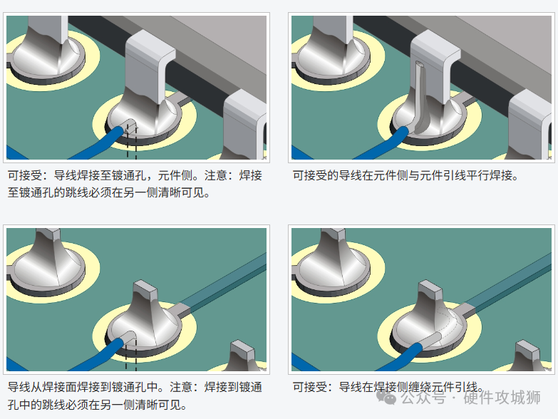
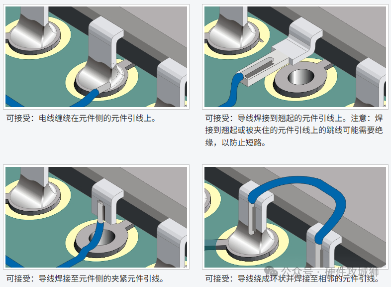
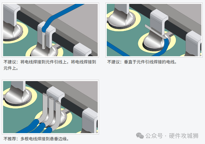
Jumper Termination Diagram – Surface-Mount Components, Pads, and Conductors
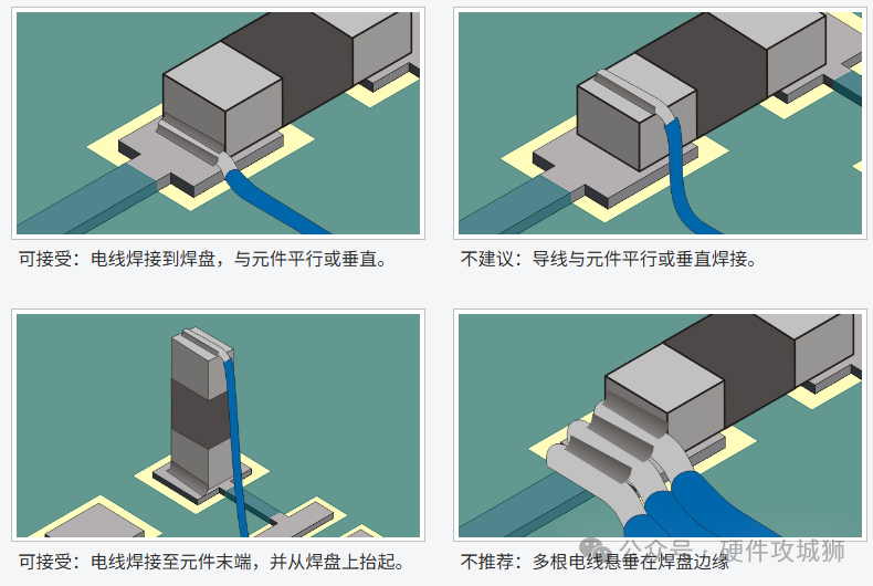
Jumper Termination Diagram – J-Lead Components
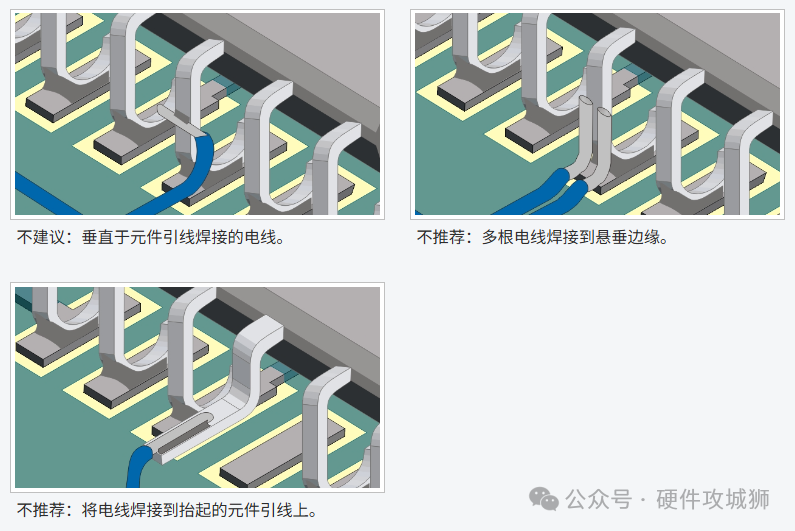
Jumper Termination Diagram – Gull-Wing Components
 — End —
Disclaimer: This account maintains neutrality regarding all original and reprinted articles’ statements and viewpoints. The articles are provided for readers’ learning and communication. Copyright for articles, images, etc., belongs to the original authors. If there is any infringement, please contact for removal.
Recommended Reading:Disassembling the Circuit Board of the U.S. Minuteman III Intercontinental Ballistic MissileDisassembling the Guidance Computer of the Titan MissileWow! I actually understood the CAN protocol in 2 days thanks to this article!Disassembly of the Tesla Model S Headlight Driver Board: An Antique Solution, No Domestic ChipsHow to Elegantly Measure Power Supply Voltage Ripple?Is there a privileged person opening back doors for their children to become developers?Want to master LDO? First, grasp these 8 basic concepts“Why do technical personnel’s assessments mostly only consider overtime? Netizens: Too real!”