Name: LCD1602 Module Driver Code Design in Verilog for Quartus Development Board
Software: Quartus
Language: Verilog
Code Function:
Design of the LCD1602 module driver code
1. Using Quartus software
2. Using Verilog language
3. Input two sets of 16-bit binary data, allowing the LCD1602 to display the string “consume” along with the first group of data converted to decimal on the first line, and the string “rest” along with the second group of data converted to decimal on the second line.
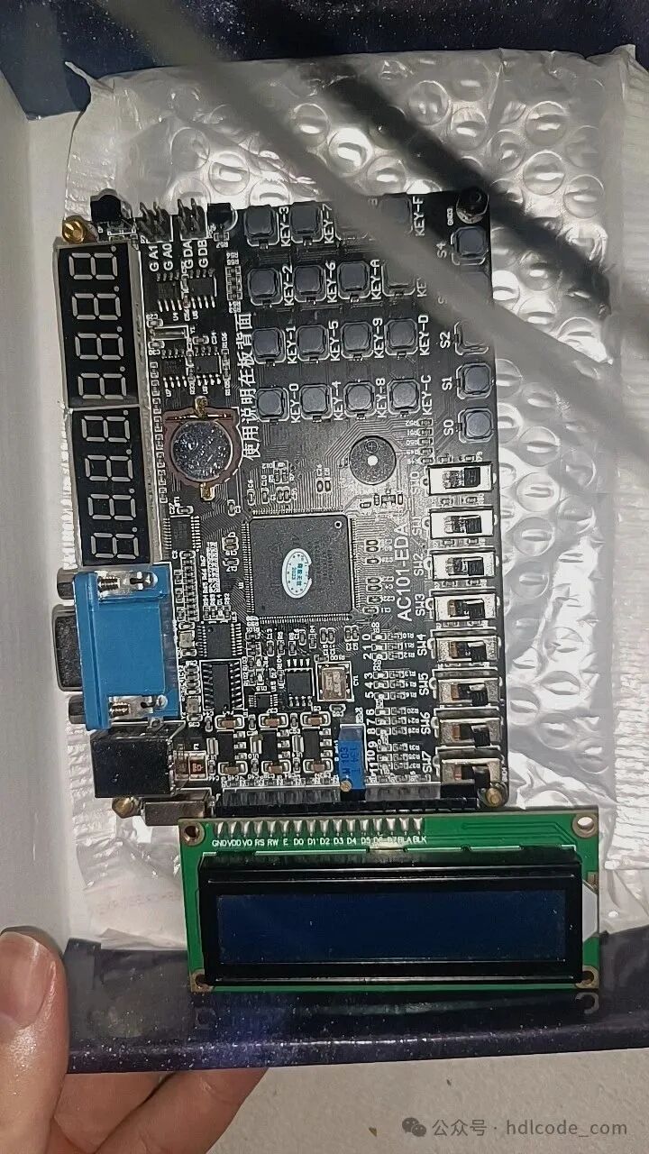
This code has been verified on the development board, as shown below. Other development boards can modify the pin assignments accordingly:
Edit
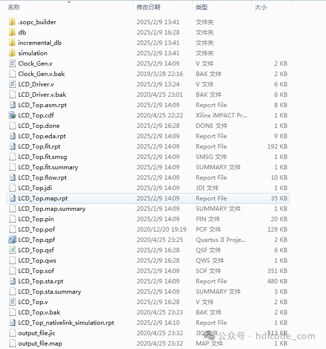
1. Project Files
Edit
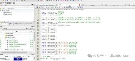
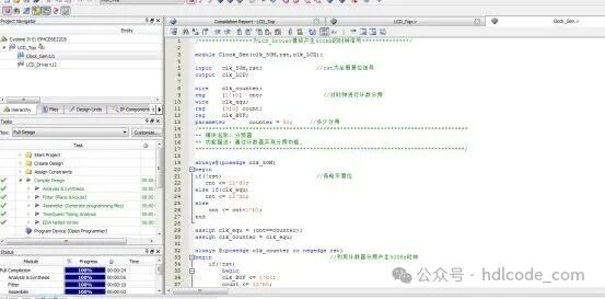
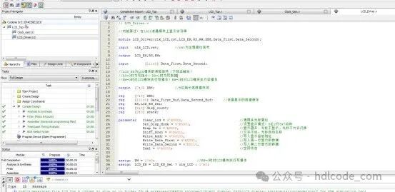
2. Program Files
Edit
Edit
Edit
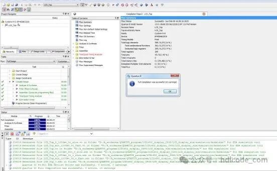
3. Program Compilation
Edit
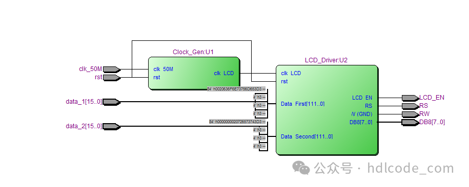
4. RTL Diagram
Edit
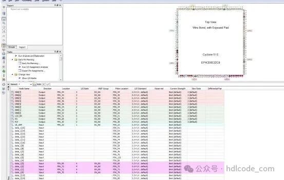
5. Pin Assignment
Edit
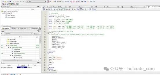
6. Testbench
Edit
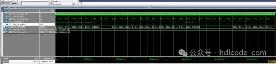
7. Simulation Diagram
Overall Simulation Diagram
Edit

Edit
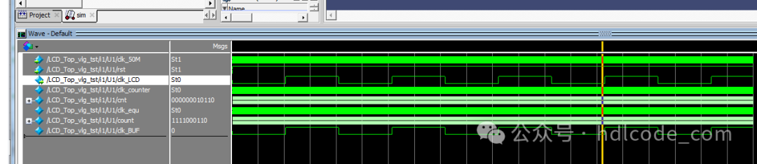
Frequency Division Module
Edit
LCD Driver Module

Edit
Partial Code Display:
// LCD_Driver.v // Function Summary: Display string on 1602 LCD module module LCD_Driver(clk_LCD,rst,LCD_EN,RS,RW,DB8,Data_First,Data_Second); input clk_LCD,rst; // rst is the global reset signal output LCD_EN,RS,RW; input [111:0] Data_First,Data_Second; // LCD_EN is the enable signal for the LCD module (falling edge triggered) // RS=0 for writing instructions; RS=1 for writing data // RW=0 for write operation to the LCD module; RW=1 for read operation from the LCD module output [7:0] DB8; // 8-bit instruction or data bus reg [7:0] DB8; reg [111:0] Data_First_Buf,Data_Second_Buf; // Data buffer for LCD display reg RS,LCD_EN_Sel; reg [3:0] disp_count; reg [3:0] state; parameter Clear_Lcd = 4'b0000, // Clear screen and reset cursor Set_Disp_Mode = 4'b0001, // Set display mode: 8-bit 2 lines 5x7 dot matrix Disp_On = 4'b0010, // Turn on display, cursor not visible, cursor not blinking Shift_Down = 4'b0011, // Text remains static, cursor moves right automatically Write_Addr = 4'b0100, // Write starting address for display Write_Data_First = 4'b0101, // Write data for the first line Write_Data_Second = 4'b0110, // Write data for the second line Idel = 4'b0111; // Idle state