Assembly Language, for those who have never delved deeply into it, can be incredibly arcane. Since our computers are developed based on assembly language, understanding this content will greatly help us clarify how the CPU works.
The X86 computer is fully backward compatible with the IBM PC – from the top level of the system to power-on startup, even down to the low-level hardware circuits, it is indeed impressive. This means that almost all PCs can run software developed after 1983; however, the cost of this compatibility is very high. The X86 architecture has gained a “bad reputation” due to its edge cases and complexity.
To understand the startup process of a modern X86 computer, we need to know the historical development of the X86 architecture; in 99% of cases, the startup process is handled by the bootloader.
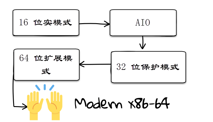
In our demo, we will focus on the 16-bit “real mode” – the operating environment of DOS systems and other variant operating systems. In this mode, the CPU does not support various security protections that modern operating systems have. Programs running in this mode can access every corner of the system and even modify it. This led to a proliferation of DOS viruses (although most of these viruses are not destructive, they are quite annoying).
In real mode, the model for interacting with hardware is also extremely simple. PCs interact with various hardware through rich external software interrupts.
This makes the initial stages of system development easier: because developers only need to know a few software interrupts to complete the vast majority of I/O operations.
After understanding this, we begin our first demo:
[BITS 16]  ; Indicates 16-bit assembly code
[ORG 0x7C00]; Starting address, informs the assembler where to load the code in memory

mov ah, 0x0A ; Set BIOS call type
mov al, 66   ; The letter to print
mov cx, 1    ; Number of times to print
mov bh, 0    ; Page number

int 0x10     ; Call BIOS to print the letter

hlt          ; Halt, the processor does nothing

TIMES 510 - ($ - $$) db 0    ; Fill the remaining space of the sector with 0
DW 0xAA55          ; Sector end identifier
What does the above code mean? The mov instruction is used to transfer data from one location to another. Here, we are only transferring data between registers and not involving memory space.<span>int</span> instruction refers to a series of software interrupts, in this code it is interrupt number 16.
Next, since we have completed our task, we call the hlt instruction to stop the CPU from running.
At this stage, you might be a bit confused about how we executed to this point? How did the computer execute these instructions?
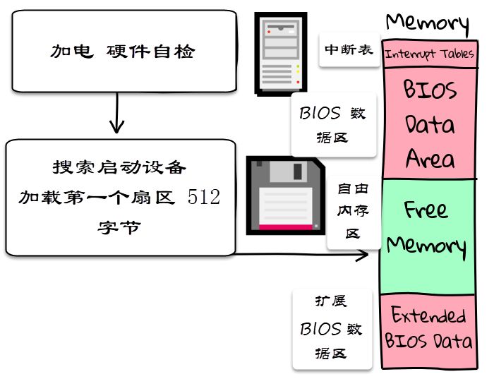
In fact, the first phase of system startup is to start the BIOS – which is used to configure and detect system hardware. At the same time, the BIOS outputs system information to the operating system program that starts next, to facilitate the subsequent hardware detection work.
Assuming the BIOS knows from which device it is booting, it will first load the first sector of 512 bytes from that device into a specified location in memory, and then jump to that location to hand over control to the next boot program.
In the above demo, the program only reads a valid payload of 512 bytes. What if the program we need to execute is larger than 512 bytes?
Fortunately, the BIOS can access the disk drives in the system by calling interrupt 13.
[BITS 16]
org 0x7C00
start:
; This section of code is added based on Michael Petch's bootloader tips
xor ax,ax ; Prepare to set DS to 0
mov ds,ax
mov bx,0x8000 ; Stack segment can be any segment of available memory
mov ss,bx ; Stack top is at 0x80000.
mov sp,ax ; Set SP=0, making the stack base at 0x90000 below
cld ; Set DF bit to forward
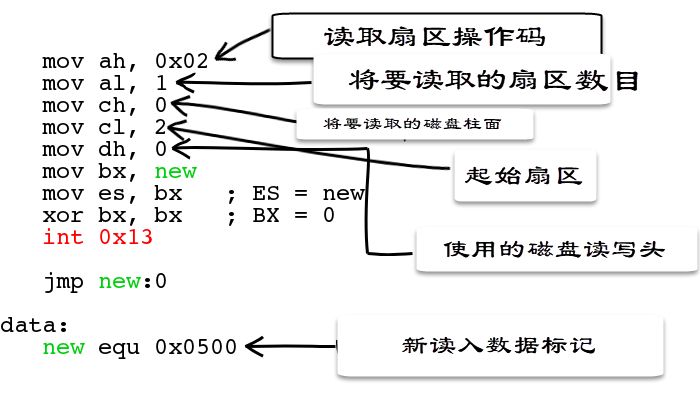
mov ah, 0x02
mov al, 1
mov ch, 0
mov cl, 2
mov dh, 0
mov bx, new
mov es, bx
xor bx, bx
int 0x13
jmp new:0
data:
new equ 0x0500
times 510-($-$$) db 0
dw 0xaa55
sect2:
mov ax, cs
mov ds, ax ; Set CS=DS. CS=0x0500, thus DS=0x500
; If the variable has already been set in the code, it requires
; to correctly reference its memory address
mov ax, 0xB800
mov es, ax
mov byte [es:420], 'H'
mov byte [es:421], 0x48
mov byte [es:422], 'E'
mov byte [es:423], 0x68
mov byte [es:424], 'L'
mov byte [es:425], 0x38
mov byte [es:426], 'L'
mov byte [es:427], 0x38
mov byte [es:428], 'O'
mov byte [es:429], 0x18
mov byte [es:430], '!'
mov byte [es:431], 0x58
hltThe above code loads the next sector of the virtual disk and then jumps to that location. The API for interrupt 13 is very concise, revealing the underlying details of how computer memory works (even though flash memory is widely used, many values are still retained for compatibility).
The services provided by the BIOS are extremely rich, and there is a great reference material:
-
http://www.ctyme.com/intr/rb-0608.htm
Appendix
Disk – Disk sector write parameter definitions
-
AH = 03h
-
AL = Number of sectors to write (must be non-zero)
-
CH = Low 8 bits of cylinder number
-
CL = Sector number 1-63 (bits 0-5)
-
High 2 bits of cylinder number (bits 6-7, only used for hard disks) DH = Number of heads
-
DL = Drive number (bit 7 set when the disk is a hard disk)
-
ES:BX -> Data buffer
Return values:
-
CF Write error
-
Set when
-
CF Cleared when write is successful
-
AH = Disk status
-
AL = Number of sectors transferred
(Valid only when the CF is set for certain BIOS)
– End –

Kanxue ID: StrokMitream
https://bbs.pediy.com/user-747320.htm
This article was translated by the Kanxue translation team StrokMitream
Source: Ben Cox @blog.benjojo.co.uk
Please indicate that it is from the Kanxue community when reprinting

Recommended Books:
Click Buy Now!

Recommended Popular Technical Articles:
-
Analysis of Seafile Cloud Disk APK’s End-to-End Encryption Method
-
VMP3.2 License Analysis
-
Introduction to Reflective DLL Technology
-
Principles of Decompilation – Control Flow Analysis

Official WeChat ID: ikanxue Official Weibo: Kanxue Security
Business Cooperation: [email protected]