Based on the main circuit diagram for controlling the forward and reverse rotation of a three-phase AC motor, design a PLC control system for the motor’s forward, stop, and reverse operations. The control requirements are as follows:
(1) Under normal conditions, press the start button SB1 to make the motor rotate forward, and press the reverse start button SB2 to make the motor rotate in reverse.
(2) After the motor starts, press the stop button SB3 and wait for 5 seconds before changing the direction of the motor’s rotation;
(3) If both SB1 and SB2 are pressed simultaneously, the motor stops and does not start, while the alarm light L1 blinks for 1 second on and 1 second off. At this time, press the SB3 stop button to reset.
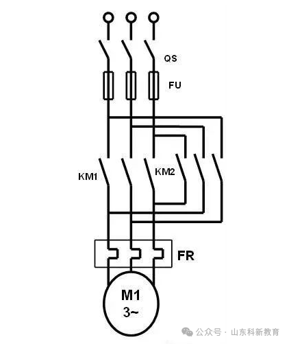
First, let’s determine the usage of the buttons and KM’s auxiliary contacts. Here is the main circuit for forward and reverse rotation, which must have an interlocking circuit. Other buttons use normally open contacts.
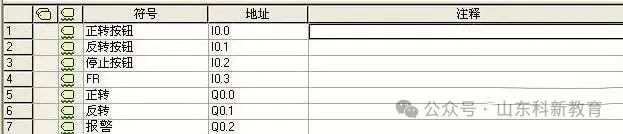
Below is the input and output point table for the PLC:
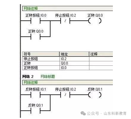
According to the requirements (1) for programming: based on requirement 1, only 2 self-holding circuits are needed.
Requirement (2) states that after pressing the stop button for 5 seconds, the motor direction can be changed, so a flag bit is needed here, using M0.0.
Additionally, add the program interlocking circuit as follows:
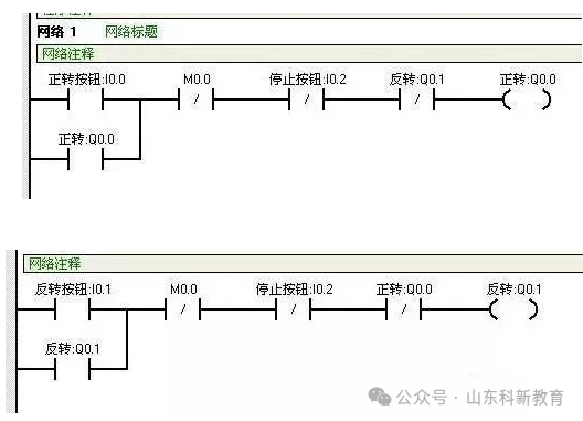
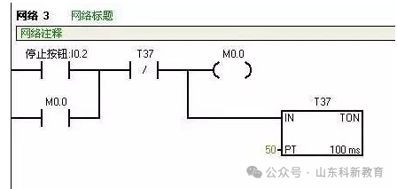
First, add the interlocking circuit in the 2 self-holding loops—network 1’s Q0.1 normally closed point and network 2’s Q0.0 normally closed point. Requirement 2 states that after pressing the stop button for 5 seconds, the start button can be pressed, so network 3 indicates that after pressing I0.2 stop button, M0.0 is powered for self-holding, and timer T37 counts for 5 seconds before stopping the self-holding circuit of M0.0. Additionally, add M0.0’s normally closed point in networks 1 and 2, so that even if the forward or reverse buttons are pressed, Q0.0 or Q0.1 will not be powered when M0.0 is powered.
Requirement (3) states that if SB1 and SB2 are pressed simultaneously, the motor stops and does not start, while the alarm light L1 blinks for 1 second on and 1 second off. The programming is as follows:
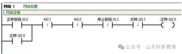
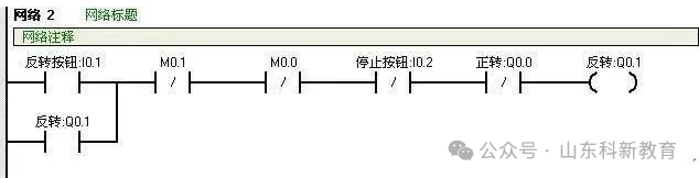
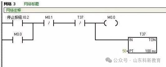
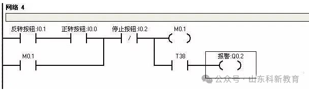
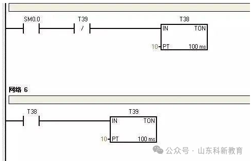
This time, networks 4/5/6 are added, where networks 5 and 6 utilize 2 timers to generate a 1-second pulse small program, with SM0.0 as a special bit that remains powered. Network 4 uses M0.1 to lock networks 1/2/3, meaning that when M0.1 is powered, networks 1, 2, and 3 do not function. The principle is the same as M0.0 in the previous section. This is the complete programming for this example. As the saying goes, a tall building rises from the ground. If you asked the author to write it all at once, it would be quite challenging. However, by breaking down the requirements step by step and writing in the necessary functions, you can certainly achieve the desired outcome. Finally, take a look at the completed program and see how much it differs from the initial program!
Source: This article is reproduced from the internet, and the copyright belongs to the original author. If there are any copyright issues, please contact us promptly for deletion. Thank you!

Scan to Follow
WeChat ID|13615417996
Follow the left QR code to get it for free
[Siemens Data Collection]