This article introduces the configuration of the free communication port in PLC programming software based on the ICE61163-3 programming standard, using Schneider’s SoMachine as an example. This is a commonly used communication method with PLC as the data acquisition object.
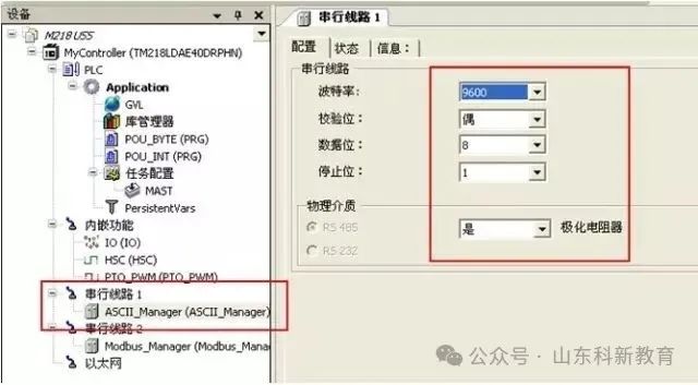
(1) Set Free Port Communication Parameters

Using the SL1 port for basic parameter settings: for example, the M218 PLC has two serial communication ports, SL1 and SL2, and we choose SL1 as the target. SL1 uses an RJ45 interface, so pay attention to the pin relationships and cable shielding when making the connection cable.
(2) Select Data Frame Format for Reception
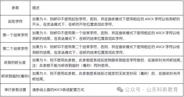
You can choose the start character and end symbol method; you can determine the end of the frame by judging the length of the data frame; or you can determine the end of the frame by frame receipt timeout (for example, if the timeout is set to 5MS, then if no other characters are received within 5MS after receiving the last character, it is judged that this frame has ended). In this example, a frame is defined as receiving 10 bytes.
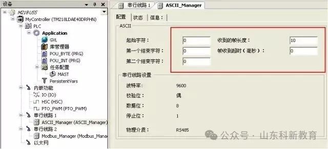
Appendix: Configuration Parameters of ASCII Manager
(3) Define Sending Register as Byte Format
The program and related data use the SEND_RECV_MSG function block. X5 and X7 are defined as BYTE type arrays. (Refer to corresponding articles for ADDM and SEND function block descriptions.)
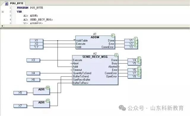
(4) Set Sending (Example Format in Hexadecimal)
X4=16#0A byte count, the data sent is the 10 bytes in the X5 array.
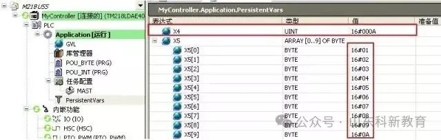
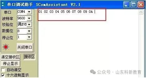
(5) Data Received by the Device
As shown in the figure below, the ten bytes received are the ten bytes of the X5 array.
(6) Ten Bytes of Data Sent by the Device

(7) Ten Bytes Received by PLC are Stored in Reception Area X7
Register
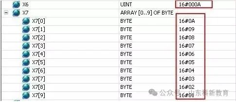
Note: If the sending register is set to INT format, for example, sending word register data 16#1234, the order received by the device will be 16#3412, which is a high-low byte order issue.
Source: This article is reproduced from the internet, copyright belongs to the original author. If there are any copyright issues, please contact us for removal. Thank you!

Scan to Follow
WeChat ID|13615417996
Follow the left QR code to get it for free
[Siemens Data Collection]