Content from: Jialichuang Community
Based on the previous use of the Renesas e2 studio development software and the basics of engineering testing, this article further explores the implementation of hardware IIC OLED text and image display.
RA0E1 Block Diagram
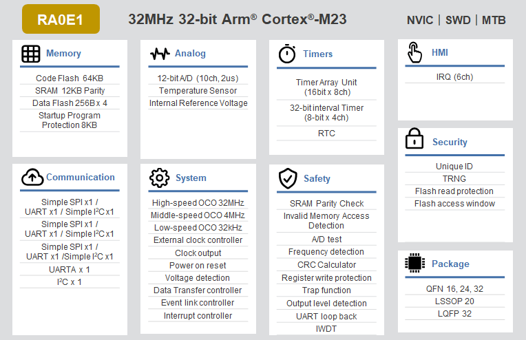
RA0E1 Features
-
32MHz Arm Cortex-M23 core
-
Up to 64KB Flash and 12KB SRAM
-
1KB data Flash (100,000 programming/erase (P/E) cycles)
-
16-pin and 32-pin package options
-
Wide voltage range from 1.6V to 5.5V
-
TAU (16-bit general-purpose PWM timer)
-
TML32 (32-bit interval timer)
-
Real-time clock
-
12-bit ADC
-
Temperature sensor
-
SAU (UART, simple SPI, simple I2C)
-
UART
-
I2C bus
-
Random number generator
-
Security features
-
+-1% high precision, high-speed on-chip oscillator
-
Flexible power architecture with fast wake-up capability
-
HAL driver code
-
Supports Arm ecosystem and Renesas’ original development tools
1
Background
Brief introduction to the IIC communication protocol, OLED display principles, and SS1306 driver IC.
IIC Communication Protocol
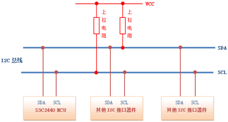
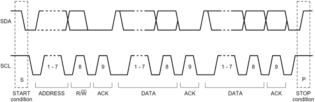
IIC (Inter-Integrated Circuit) is an integrated circuit bus. It is a serial communication bus that uses a multi-master/slave architecture, as shown in the diagram.
(You can copy the link below to your browser or scan the QR code to view)
IIC
Philips designed it in the early 1980s, originally to allow motherboards, embedded systems, or mobile phones to connect to low-speed peripheral devices.
Since October 1, 2006, using the IIC protocol does not require a patent fee, but manufacturers still need to pay to obtain IIC slave device addresses.
Features of the IIC Communication Protocol are as follows
-
Only requires two bus lines
-
No strict baud rate requirement, for example, using RS232, the master generates the bus clock
-
All components have a simple master/slave relationship, and each device connected to the bus can be software-addressed by a unique address
-
IIC is a true multi-master bus, providing arbitration and conflict detection
(You can copy the link below to your browser or scan the QR code to view)
Multi-master
IIC uses two wires for communication: one clock line SCL and one data line SDA.
The action of pulling SDA low while SCL is high is the start signal, and the action of pulling SDA high while SCL is high is the end signal;
When transmitting data, SDA changes data while SCL is low, and holds data while SCL is high, with each SCL pulse high level transmitting 1 bit of data.
7-bit Device Data Transmission
-
Software-simulated IIC generally uses GPIO pins, with software controlling the high and low level output of the pins to simulate the IIC communication waveform.
-
Hardware IIC corresponds to IIC peripherals on the chip, with corresponding IIC driver circuits, and the IIC pins used are also dedicated.
Comparison of Software and Hardware IIC
-
Hardware IIC efficiency is much higher than software IIC; software IIC is not limited by pins, making the interface more flexible;
-
Software-simulated IIC works by simulating the operation of GPIO software registers, while hardware IIC directly calls internal registers for configuration;
-
In terms of performance, hardware IIC has higher reliability and stability due to being processed by dedicated hardware modules, reducing software interference;
-
Hardware IIC modules can automatically handle data transmission in the background, freeing up CPU resources, resulting in lower CPU usage;
-
The code size for software IIC is larger than that for hardware IIC, making it more complex in comparison;
-
Hardware IIC typically also supports higher communication rates.
OLED Display Principles
OLED (Organic Electroluminescence Display) refers to organic light-emitting diodes.
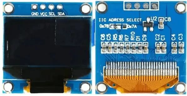
Due to its self-emitting capability, no need for a backlight, high contrast, thin thickness, wide viewing angle, fast response speed, applicability to flexible panels, wide temperature range, and simpler construction and manufacturing process, OLED is regarded as the emerging application technology for next-generation flat displays.
Basic Parameters of 0.96-inch OLED
-
Operating voltage: 3.3~5V (with built-in 3.3V LDO, IIC communication interface level is 3.3V)
-
Pixel matrix size: 128*64 (128 columns, 64 rows, total of 8192 LEDs)
-
Driver IC: SSD1306
OLED Module Circuit
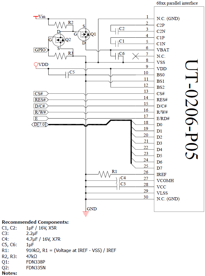
SSD1306 Driver Circuit
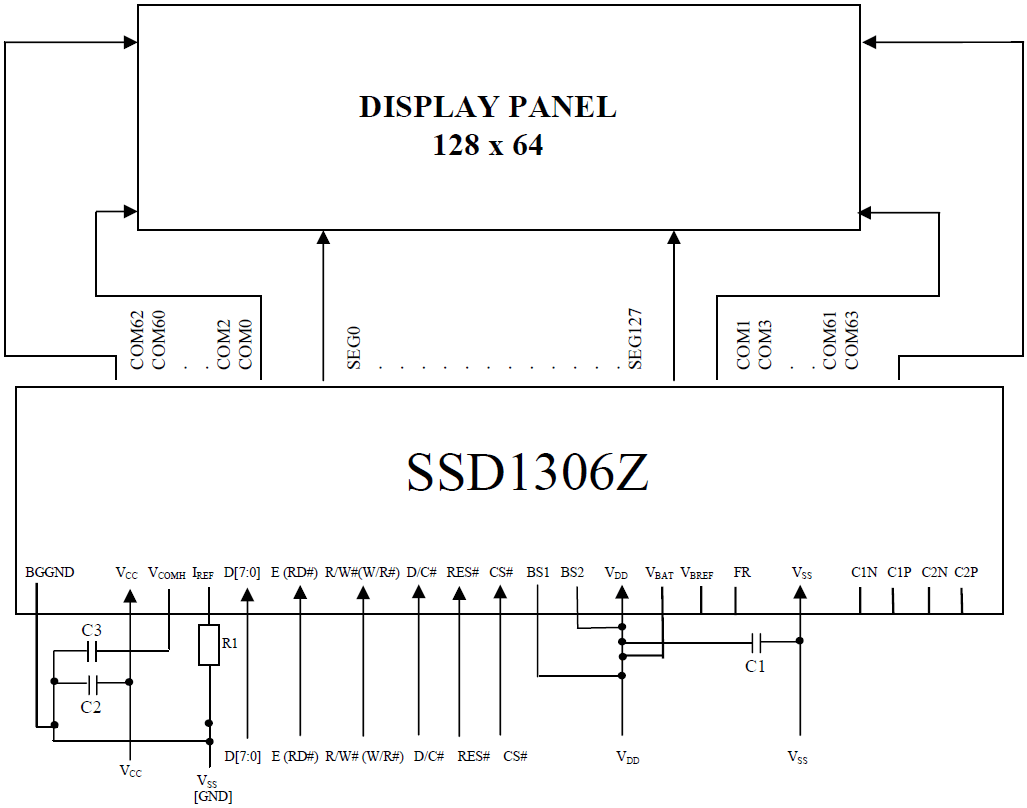
See: oled I2c, SSD1306 Datasheet.
(You can copy the link below to your browser or scan the QR code to view)
oled I2c, SSD1306 Datasheet.
https://www.alldatasheet.com/datasheet-pdf/pdf/1179026/ETC2/SSD1306.html
2
Method Description
-
Use e2 studio to establish the hardware IIC framework;
-
Compile the main functions related to OLED, especially the initialization, opening IIC, writing to IIC, etc., or transplant related functions and make modifications;
-
Run the program, build the project, and debug the project.
3
Operation Instructions
-
Create a new project;
-
Define pin Pins;
-
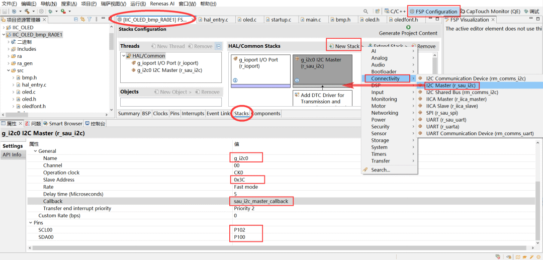
Create Stacks – IIC master, modify properties, and define address 0x3C;
-
Transplant and modify oled.c, oled.h, oledfont.h, bmp.h files;
-
Build the main function hal_entry.c, debug the project.
4
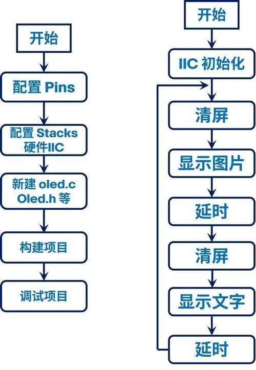
System Block Diagram
5
Code
Main Function
hal_entry.cSwipe left and right to view the full content
while(1){ /*---------- Picture ------------*/ OLED_Clear();//clear screen OLED_DrawBMP(0,0,128,8,BMP1); R_BSP_SoftwareDelay(500, BSP_DELAY_UNITS_MILLISECONDS); /*----------- Text ------------*/ OLED_Clear();//clear screen OLED_ShowString(0,0,"RA",16); OLED_ShowCHinese(16,0,0);//生 OLED_ShowCHinese(32,0,1);//态 OLED_ShowCHinese(48,0,2);//工 OLED_ShowCHinese(64,0,3);//作 OLED_ShowCHinese(80,0,4);//室 OLED_ShowString(0,2,"2024.12.14",16); OLED_ShowString(0,4,"Renesas RA0E1",16); R_BSP_SoftwareDelay(500, BSP_DELAY_UNITS_MILLISECONDS);}oled.coled.holedfont.hbmp.h6
Results
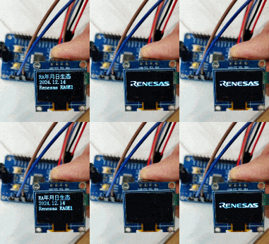
As shown in the main code, images and text are displayed alternately.
Swipe left and right to view the full content
while(1){ /*---------- Picture ------------*/ OLED_Clear();//clear screen OLED_DrawBMP(0,0,128,8,BMP1); R_BSP_SoftwareDelay(500, BSP_DELAY_UNITS_MILLISECONDS); /*----------- Text ------------*/ OLED_Clear();//clear screen OLED_ShowString(0,0,"RA",16); OLED_ShowCHinese(16,0,0);//生 OLED_ShowCHinese(32,0,1);//态 OLED_ShowCHinese(48,0,2);//工 OLED_ShowCHinese(64,0,3);//作 OLED_ShowCHinese(80,0,4);//室 OLED_ShowString(0,2,"2024.12.14",16); OLED_ShowString(0,4,"Renesas RA0E1",16); R_BSP_SoftwareDelay(500, BSP_DELAY_UNITS_MILLISECONDS);}The page refreshes every 500ms.
7
Demonstration Video
8
Insights
The Renesas RA0E1 chip has excellent features such as high performance, power efficiency, and cost-effectiveness. Coupled with Renesas’ complete development environment, convenient operations, and GPIO configurations, IIC configurations, etc., it enables rapid development and debugging of projects.
Thanks to Jialichuang and Renesas for hosting the development board trial activities. It is hoped that this event and related evaluations can provide references for many electronics enthusiasts and be applied in future projects.

Need product and solution support
Please scan to register

Need technical support?
If you have any questions while using Renesas MCU/MPU products, you can identify the QR code below or copy the URL into your browser to enter the Renesas Technical Forum to find answers or get online technical support.
https://community-ja.renesas.com/zh/forums-groups/mcu-mpu/
1
END
1
Recommended Reading
Excellent case sharing from the Lichuang Electric Competition: “Animated Clock”
Excellent case sharing from the Lichuang Electric Competition: “Desktop Clock Design Based on Renesas”
Excellent case sharing from the Lichuang Electric Competition: “Touch Light Strip Controller”
For more exciting content, please stay tuned


Need product and solution support
Please scan to register