1
UART
UART is an asynchronous serial communication protocol, with the full English name Universal Asynchronous Receiver/Transmitter. Unlike communication protocols such as SPI and I2C, it is also a commonly used IP in SoCs. Its greatest advantage is that it uses only two wires for communication, supporting full-duplex, meaning one wire (UTx) is used for sending data, while the other wire is used for receiving data. The communication between two UARTs is shown in the figure below:
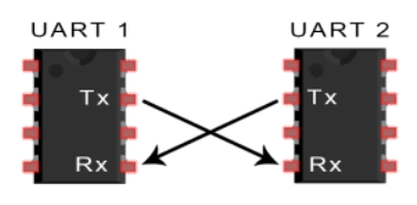
The sending UART may convert parallel data from a controlling device (such as a CPU) into serial form and send it to the receiving UART, which then converts the serial data back into parallel data for the receiving device. Data flows from the Tx pin of the sending UART to the Rx pin of the receiving UART.
2
Working Principle of UART
UART is asynchronous communication, which means there is no clock signal for data sampling synchronization. Therefore, the sending side of the UART needs to add start and stop bits to the data packets being transmitted. These bits define the beginning and end of the data packet, allowing the receiving UART to know when to start reading these bits. When the receiving UART detects the start bit, it begins reading the input bits at a specific frequency known as baud rate. The baud rate is a measure of data transmission speed, expressed in bits per second (bps). Both UARTs must operate at approximately the same baud rate. The baud rate between the sending and receiving UARTs can only differ by about 10%. Additionally, both UARTs must be configured to send and receive the same data packet structure.
3
How UART Works
-
Other devices (such as CPUs, memory, or microcontrollers) send data to the UART via a data bus. The sending UART first receives data from the data bus.

-
Data is transmitted in parallel form from the data bus to the sending UART. After the sending UART retrieves the parallel data from the data bus, it adds start bits, parity bits, and stop bits to create a data packet.

-
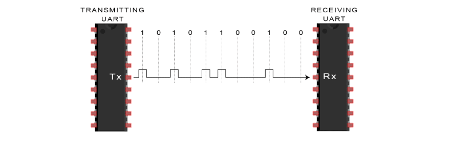
The data packet is serially output bit by bit on the Tx pin, while the receiving UART reads the data packet bit by bit on its Rx pin.
-
Then, the receiving UART converts the data back into parallel form and removes the start bits, parity bits, and stop bits.

-
The receiving UART then transmits the data packet in parallel to the data bus of the receiving end.

4
UART Frame Structure
The data transmitted by UART is organized into packets. Each packet contains 1 start bit, 5 to 9 data bits (depending on the UART), an optional parity bit, and 1, 1.5, or 2 stop bits.
Start Bit
The UART data transmission line typically remains at a high voltage level when no data is being transmitted. To start data transmission, the sending UART pulls the transmission line from high level to low level within one clock cycle. When the receiving UART detects the transition from high voltage to low voltage, it begins reading the bits in the data frame at the baud rate frequency.
Data Bits
The data frame contains the actual data being transmitted. If a parity bit is used, it can be 5 bits, up to 8 bits. If no parity bit is used, the length of the data frame can be 9 bits. In most cases, the data is sent starting with the least significant bit.
Parity Bit
This bit is used by the receiver for data integrity and correctness checks. It is optional and can be configured as odd parity/even parity/no parity/parity bit always 1/parity bit always 0 options.
Stop Bit
To signal the end of the data packet, the sending UART drives the data transmission line from low level to high level for at least the duration of two bits.
5
Advantages and Disadvantages of UART
Advantages
-
Data is transmitted using only two wires.
-
No clock signal is required.
-
Includes parity bits for error checking.
-
Simple send/receive protocol.
Disadvantages
-
Maximum data frame size is 9 bits.
-
Slower transmission speed.
- The baud rate of each UART must be within 10% of each other.
● END ●

If you like it, please click “Like”.