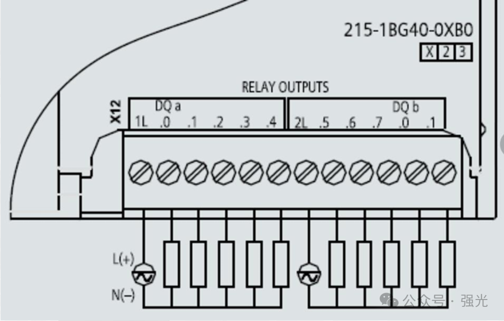
Digital Input
Digital inputs can be used to collect switch signals, commonly used components include: buttons, limit switches, proximity switches, photoelectric switches, etc.
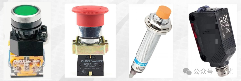
Wiring Methods for Buttons and Switches
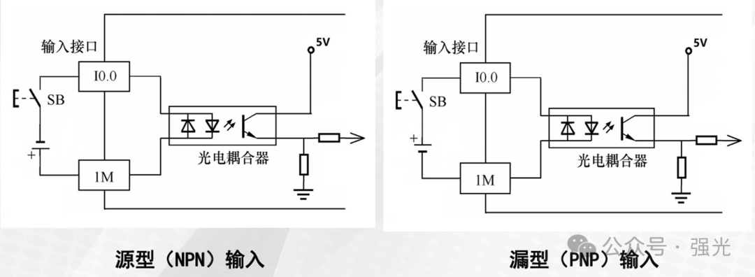
The PLC input points are opto-isolated, and when the light source of the opto-isolator emits light, the PLC can receive the signal.
There are two wiring methods to make the light source of the opto-isolator emit light:
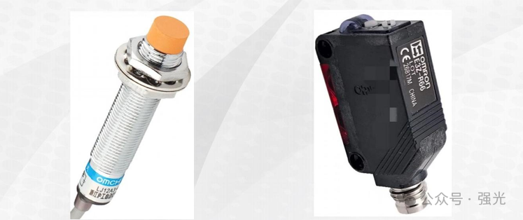
Wiring Methods for Sensors
The wiring method for sensors is the same as that for switches, with the purpose of making the light source of the opto-isolator emit light.
The wiring for the sensor is:Brown positive, blue negative, black signal wire.When the sensor detects an object, the black wire will output eitherOV or 24V voltage.
If the black wire outputsOV, then the sensor is of theNPN type.
If the black wire outputs24V, then the sensor is of thePNP type.
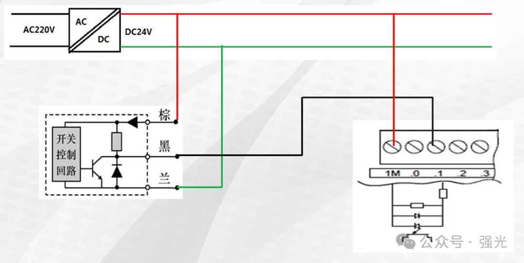
NPN Sensor Wiring
ForNPN type sensors connected to the PLC, the common terminal 1M is connected to 24V+, this wiring method is called source type wiring or common anode wiring.
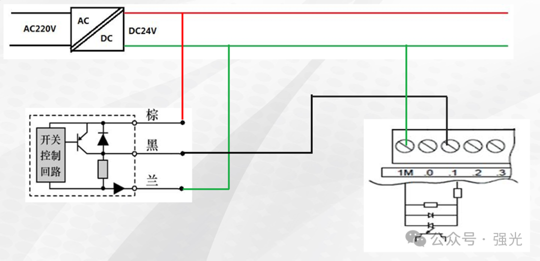
PNP Sensor Wiring
ForPNP type sensors connected to the PLC, the common terminal 1M is connected to OV, this wiring method is called sink type wiring or common cathode wiring.
Digital Output
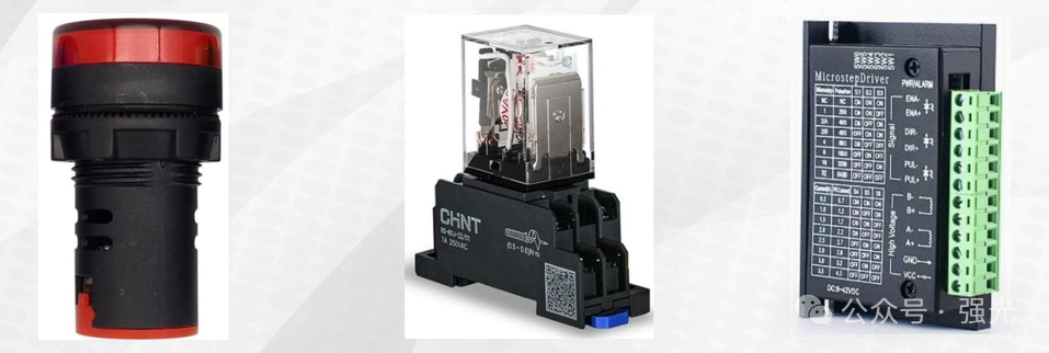
Digital outputs can be used to connect to indicator lights or relay coils and other loads, commonly used components include: indicator lights, alarm buzzers, relay coils, stepper drivers, or servo drivers, etc.
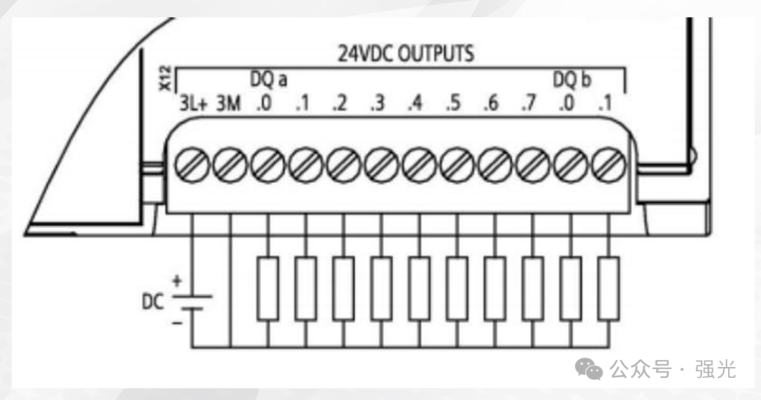
Transistor Type Wiring
In Siemens PLCs, there are two types of outputs, relay type and transistor type. The relay type can output 5-30V DC or 5-250V AC, while the transistor type outputs 24V DC. The following is the wiring for the transistor type:
Relay Type Wiring
Relay type wiring is slightly different; the relay type can output 5–30V DC or 5-250V AC.
The common terminalL is connected to the voltage, the PLC will output the same voltage.