Kingst’s LA5016 Logic Analyzer is a highly popular mid-range desktop logic analyzer, renowned among electronic engineers and enthusiasts for its excellent cost-performance ratio and powerful features.
1. What is LA5016? Core Function Overview
LA5016 is a desktop logic analyzer produced by Kingst with a 500 MHz sampling rate and 16 digital channels. You can think of it as a “microscope for the digital world” or a “monitor for software execution” for electronic circuits.
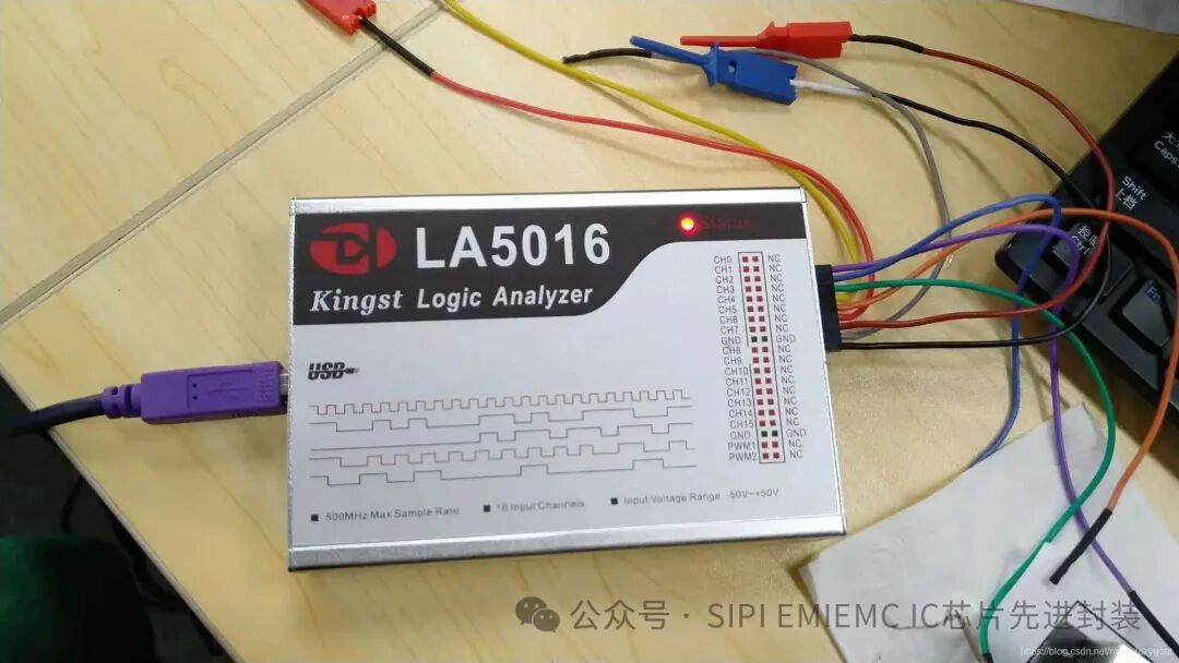
Its core task is to capture, display, and analyze signals (high and low level changes) in digital circuits, helping you deeply debug issues that arise during hardware and software interactions.
Main Features:
-
High Sampling Rate and Depth:
-
500 MHz timing sampling rate: Accurately measures high-speed digital signals, capturing very brief level transitions (with a minimum resolvable pulse of 2 ns).
-
100 Mpts (million sample points) storage depth per channel: Allows for long-term signal recording, ensuring sufficient recording time even when capturing high-speed signals, without missing critical information. This is a key advantage over cheaper logic analyzers.
Multi-channel Analysis:
-
16 digital channels: Can monitor 16 signal lines simultaneously (e.g., an 8-bit data bus + several control signal lines), making it ideal for analyzing parallel buses.
Powerful Triggering Functions:
-
Can set complex triggering conditions, such as edge triggering, pulse width triggering, and under-amplitude pulse triggering, as well as advanced protocol triggering (such as specific addresses, data, or commands for I2C, SPI, UART). It will only capture and display waveforms when your set conditions are met, allowing you to precisely “catch” the events you want to see.
Protocol Decoding: I2C, SPI, etc.
-
This is the most core and practical function of the logic analyzer. The LA5016 has built-in decoders for many common serial protocols, such as:
-
It can not only display the high and low levels of waveforms but also directly translate waveforms into human-readable protocol data (e.g., “Start”, “Addr: 0x68 W”, “Data: 0x12”, “Stop”), greatly improving debugging efficiency.
Mixed Signal Analysis (MSO Concept):
-
Although the LA5016 is a pure logic analyzer, many RIGOL oscilloscopes (such as the MSO5000 series) can use it as an extension module, triggering and displaying the oscilloscope’s analog channels alongside the LA’s digital channels for true mixed signal analysis.
2. Typical Application Scenarios for LA5016
-
Digital Circuit Debugging: Finding glitches, timing conflicts, signal integrity issues, etc.
-
Embedded Software Debugging: Verifying whether the software correctly controls hardware pins (e.g., GPIO outputs).
-
Serial Bus Analysis: Debugging I2C, SPI sensors, UART communication, CAN bus communication, etc. This is the most commonly used function.
-
Reverse Engineering: Analyzing the communication protocols of unknown devices.
-
Teaching and Learning: Deepening the understanding of digital logic and communication protocol principles.
3. Hardware and Software Components
-
Main Unit: The LA5016 desktop device itself.
-
Probes and Cables:
-
Typically equipped with a flying lead probe box, which has 16 channels (D0-D15) and a GND grounding clip.
-
One end of the probe has Dupont pins (female), used to connect to test points on the circuit board being tested.
Software: Requires installation of “Ultra Analyzer” software on the computer. The LA5016 connects to the computer via USB, and all operations and data analysis are performed in the computer software.
4. Operating Procedure (Debugging an I2C Temperature Sensor as an Example)
Step 1: Connect Hardware
-
Connect the LA: Use a USB cable to connect the USB Device port of the LA5016 to the computer. The computer will recognize a device.
-
Install Software: Install and run the Ultra Analyzer software on the computer.
-
Physical Wiring:
-
Securely connect the probe box’s GND wire (black) to the ground (GND) of the circuit being tested. This is the most critical step; if the ground is not connected properly, it will cause signal confusion!
-
Connect the probe for channel D0 to the SCL (clock line) pin of the sensor.
-
Connect the probe for channel D1 to the SDA (data line) pin of the sensor.
-
(Optional) If analyzing a parallel bus, you can sequentially connect D2, D3… to the data/address bus.
Step 2: Basic Software Settings
-
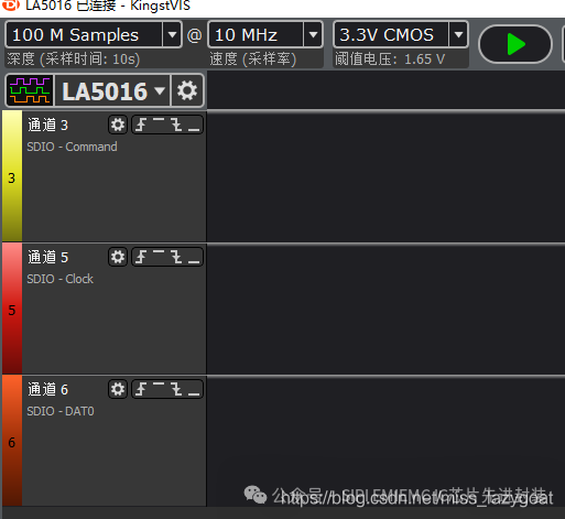
Open Software and Connect Device: Run Ultra Analyzer; the software will usually automatically discover and connect to the LA5016.
-
Configure Acquisition Parameters:
-
Sampling Rate: Set to 100 MHz (for the common I2C 400kHz rate, a 100MHz sampling rate is already high enough to ensure waveform accuracy).
-
Sampling Depth: Set to 1 Mpts or higher (the larger the depth, the longer the time window that can be captured).
-
Threshold Voltage: Set to the logic level standard of the circuit being tested. For a 3.3V system, it is usually set to around 1.65V; for a 5V system, set to 2.5V. This setting tells the instrument how to determine high and low levels.
Step 3: Set Trigger (Capture Specific Data)
We do not want to see all waveforms; we only want to see the moment the microcontroller reads the temperature.
-
Select Trigger Type -> Protocol Trigger -> I2C.
-
Specify Channels: Assign SCL to D0 and SDA to D1.
-
Set Trigger Conditions: For example, we want to capture the moment of sending the read command to the sensor (address 0x68) for the data register (0x00).
-
Click the “Run” or “Single” button on the software, and the instrument will start waiting for the trigger conditions.
Step 4: Run and Capture
-
Let the system under test start working (e.g., reset the microcontroller to begin reading the sensor).
-
When the microcontroller issues an I2C command that meets the trigger conditions, the LA5016 will be triggered immediately, capturing all waveforms from a period before and after the trigger point and uploading them to the computer software.
Step 5: Analyze and Decode
-
View Raw Waveform: The main interface of the software will display the high and low level waveforms captured on D0 and D1.
-
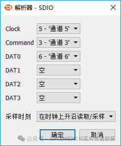
Add Protocol Decoding:
-
Find the “Decode” or “Analysis” menu in the software.
-
Add an I2C Decoder.
-
Specify the channels corresponding to SCL and SDA (D0, D1).
Read Results:
-
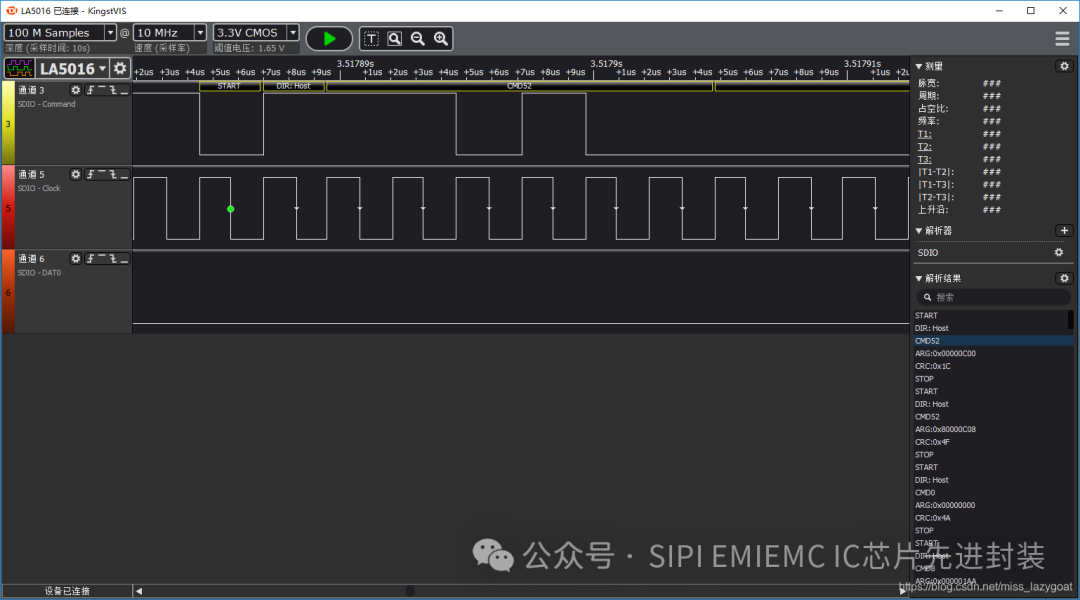
The software will automatically generate a decoding result window below the waveform.
-
This will clearly display the start bit, address bit (and read/write direction), acknowledge bit, data bytes, stop bit, etc. in the form of data packets.
-
You can directly see the read temperature data value (e.g.,
<span>Data: 0x1A 0x00</span>), without having to count pulses yourself.
Step 6: Measurement and Diagnosis
-
Cursor Measurement: Using the cursor function in the software, you can accurately measure the time interval between any two points in the waveform, checking whether timing parameters such as clock frequency, data setup/hold times are compliant.
-
Search: If the captured data is long, you can use the search function to quickly find the location of a specific address or data packet.
5. Advantages and Precautions
Advantages:
-
Professional and Powerful: Compared to simple logic analyzers costing a few dozen yuan, the sampling rate, storage depth, stability, software functionality, and accuracy are several orders of magnitude better.
-
Protocol Decoding: Complete and accurate functionality, making it a productivity tool.
-
Ease of Use: The Ultra Analyzer software interface is intuitive, with a relatively gentle learning curve.
Precautions:
-
Grounding is Key: Ensure that the probe ground wire and the circuit board ground are reliably connected; otherwise, the signal will oscillate and distort.
-
Probe Loading Effect: The probe will introduce additional capacitance into the circuit, which may affect very high-speed signals (>100MHz), but this is generally not a concern for most embedded applications.
-
Setting Trigger Conditions: Trigger conditions need to be set reasonably based on debugging objectives to efficiently capture issues.
In summary, the LA5016 is a comprehensive and powerful desktop debugging tool, especially adept at solving complex issues at the digital communication protocol level, making it an indispensable tool for embedded hardware engineers.